CrispinM
Registered
I am brand new to this, so feel free to use small words and pictures.
I have a loco with a decoder I installed (PIKO 36220 American Steam Sound with Decoder kit, DC/DCC).
My tracks are continuously getting a buildup of pollen/tarnish and so I want to install a capacitor to address this issue.
The PIKO wiring diagram for the decoder (attached) shows where to add an "optional capacitor".
I've ordered 2 Full CurrentKeepers at the advice of the people at SoundTraxx and they have sent me their recommended wiring diagram for installation (also attached).
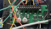
Also attached is a photo of the actual decoder I installed.
My questions are:
Here is the SoundTraxx advice from the email they sent:
You will likely need 2 full CurrentKeepers attached. The decoder/sound system was not designed with stay alive to be simply plugged in (Not a request from Piko) so to do this, you will need 2 separate ones, one for the motor and a second for the processor/audio, etc.. A small cap would not likely be enough to maintain power for more than ½ sec, with the bigger current draw of the motor.. So, I have attached the diagram from our engineering department that shows where to connect these CK/Capacitors to the PCB.
Note, you will be soldering to the PCB, and we cannot be liable for any mishandling or errors in attaching to the decoder. Make sure you are using proper soldering materials for work on PCBs, including a fine-tip adjustable-temperature soldering iron, a small fine diameter solder and a flux that is designed for PCBs and microelectronics rather than what is normally available from the hardware store that is high in acid that can attack and cause parts to fail. For more on soldering, refer to Webinar 8: SoundTraxx Soldering Class (webinar 8) Any damage to the PCB cannot be warrantied, and any warranty/repair on the Piko boards have to go back through Piko.
I hope this helps. Let us know if you need any further assistance.
I have a loco with a decoder I installed (PIKO 36220 American Steam Sound with Decoder kit, DC/DCC).
My tracks are continuously getting a buildup of pollen/tarnish and so I want to install a capacitor to address this issue.
The PIKO wiring diagram for the decoder (attached) shows where to add an "optional capacitor".
I've ordered 2 Full CurrentKeepers at the advice of the people at SoundTraxx and they have sent me their recommended wiring diagram for installation (also attached).
Also attached is a photo of the actual decoder I installed.
My questions are:
- Will one of these capacitors installed according the PIKO wiring diagram adequately address all my dirty track problems for this loco (power the motor/sound/lights when necessary). This seems to be the easier way, but I'm only interested in it if it's also the best way. If it is the best way, should I put two in?
- If I use the SoundTraxx diagram and put two in, will I need to do anything to the area indicated in order to solder them in the right spot? Do the little black plastic pieces on the silver elements the diagram is pointing to come off? Do I simply carefully solder to the exposed part the blue lines are pointing to? I can see that the rectangles do seem to have one end that's more exposed on the indicated ends and that's comforting as far as knowing I'm looking at it correctly.
- For the black lines on the SoundTraxx diagram, do both of those get screwed down into that third slot in the bell whistle area? It's the same place that one of the wires goes on the PIKO optional capacitor instructions with the other wire going to an unused screw position (4th from the left) in their diagram.
- How do I cover/heatshrink tube the part so it doesn't pose a short circuit problem when I'm done?
- In general, where do I find diagrams for boards like this or place to look up and learn what all the little elements on these boards are?
Here is the SoundTraxx advice from the email they sent:
You will likely need 2 full CurrentKeepers attached. The decoder/sound system was not designed with stay alive to be simply plugged in (Not a request from Piko) so to do this, you will need 2 separate ones, one for the motor and a second for the processor/audio, etc.. A small cap would not likely be enough to maintain power for more than ½ sec, with the bigger current draw of the motor.. So, I have attached the diagram from our engineering department that shows where to connect these CK/Capacitors to the PCB.
Note, you will be soldering to the PCB, and we cannot be liable for any mishandling or errors in attaching to the decoder. Make sure you are using proper soldering materials for work on PCBs, including a fine-tip adjustable-temperature soldering iron, a small fine diameter solder and a flux that is designed for PCBs and microelectronics rather than what is normally available from the hardware store that is high in acid that can attack and cause parts to fail. For more on soldering, refer to Webinar 8: SoundTraxx Soldering Class (webinar 8) Any damage to the PCB cannot be warrantied, and any warranty/repair on the Piko boards have to go back through Piko.
I hope this helps. Let us know if you need any further assistance.

