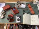
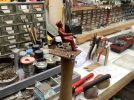
Another Pway Trolley, this time a PippaPig Bash with a little Newquid and LGB thrown in.

dunnyrail

DOGS, Garden Railways, Steam Trains, Jive Dancing,
Staff member
GSC Moderator
Country flag
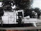
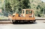
So we have had sundry conversations about the PeppaPig Railbus on the Forum and I eventually gave way and bought one. This conversion is a quite memory bashing one as starting it today 7 years after my good friend Andy Rush of Ruschbahn fame passed away, he would have been pleased to see a few of his Newquid and LGB bits being repurposed in this way. First a couple of pics of what I am intending to make a look alike of. Though whether a Crane will be involved remains to be seen.
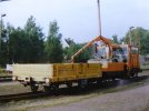
9E530F2C-9BA3-4910-89A2-2E1BF16D7A65.jpeg
1A5427DE-C03E-45C5-9449-F3F65BE1D519.jpeg
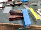
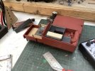
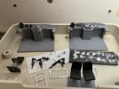
Here are the sundry bits laid out. Note that I going to use an IP Budget chassis, though if I can I hope to get Metal Gears to replace the nylon ones, the chassis is already 4 wheel drive having been fitted with Delrin Chain.
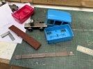
9222D76E-346B-4183-8B15-F5F50B3B152A.jpeg
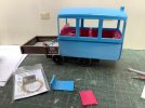
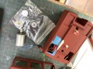
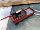
I have cut up the Newquid sides and they have been used to make a 2 plank high freight section. These have been glued together after some shortning and Filing of ridges to get neat joints. These are sitting on an off-cut piece of 2mm clear plastic sheet that I happened to have an off-cut that was just over just the right size required of 72 mm wide 78 mm long. The trolley will be powered by 4 aa NiMh Batteries and have a Deltang Rx45 RC receiver. Thius below you see progress up to now.
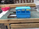
AA84FC6B-235B-421F-8B7E-C57C0D4B1235.jpeg
 
Last edited:
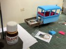
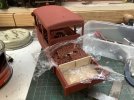
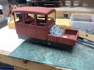
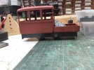
Have been doing a bit more hacking and cutting to get things in shape. Firstly I carried out some some serious sanding to remove unwanted door, moulding and rear lamp detail. As can be seen below I wedged a block or two of Wood into the body to lightly raise where the detail was being difficult to remove. This was then lightly sanded to give a good surface for spray painting. The front lights, rad and wing mirrors have all been left in place. I do want this to be recognisable for what it was.
7E3F01BD-4CC9-4F41-ADF0-A551B49242E6.jpeg
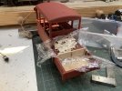
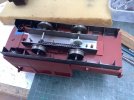
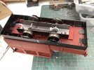
Next I have cut out for the Motor to fit the rear and main body, this has been arranged so that there is an equal overhang both front and rear of roughly 40mm. 8ba screws hold the rear base and body base onto the motor unit. The open wagon part is just plonked on for effect. Further hacking to the red inside has been done to allow this to sit in as well, the original screws hold it to the base of the unit. I could attach a couple of batteries now and would happily trundle round the layout. But first I need to ponder where I will fit 4 x AA NiMh Batteries, the on/off Switch and charging socket. The Rx will be no problem at all being so small. I also want to preserve the roof part lifting off, this will allow access to the switch and charging socket. It may be that batteries will have to sit in the rear of the cabin perhaps under some fake bench seats.
82BDD567-1566-4D72-A3DD-0ED61E8DB28F.jpeg
228A391B-9196-497B-8FA4-769A4B339F4E.jpeg
 
I started out the day with the prospect of getting this wired up. All went well and it test worked with the spare chassis just fine, then the new gears appeared just as I had proved all to be working.
CB3FA040-117B-4BDE-9AAC-62E011C04577.jpeg
Below can be seen the new gears as delivered by IP Engineering, the old ones are still on the motor and the yellowish one just above. So I fitted the new gears and wired up the chassis. Just as I was thinking that I could put this all to bed to get on with the rest of the detail and body work. Bleeding disaster, chassis works ok forwards but stop and put in reverse the motor does about half a wheel revolution then the Deltang Rx45b-22 light starts flashing as the motor stops rotating. Have lightly oiled the axles and a little bit of LgB grease on the gears but hm. Have tested the the chassis on an independent 6 v battery supply and no problems in either direction so I do not suspect a dodgy set of gears. CB3FA040-117B-4BDE-9AAC-62E011C04577.jpegAny ideas anyone?
 

Attachments

  • 3419769D-078E-42E9-9B71-BB2F07E18E72.jpeg
    3419769D-078E-42E9-9B71-BB2F07E18E72.jpeg
    631.8 KB · Views: 0
I started out the day with the prospect of getting this wired up. All went well and it test worked with the spare chassis just fine, then the new gears appeared just as I had proved all to be working.
View attachment 271258
Below can be seen the new gears as delivered by IP Engineering, the old ones are still on the motor and the yellowish one just above. So I fitted the new gears and wired up the chassis. Just as I was thinking that I could put this all to bed to get on with the rest of the detail and body work. Bleeding disaster, chassis works ok forwards but stop and put in reverse the motor does about half a wheel revolution then the Deltang Rx45b-22 light starts flashing as the motor stops rotating. Have lightly oiled the axles and a little bit of LgB grease on the gears but hm. Have tested the the chassis on an independent 6 v battery supply and no problems in either direction so I do not suspect a dodgy set of gears. View attachment 271258Any ideas anyone?
You have only got 4.8 volts to the motor (yep I know you said you tested it with 6v) might make a difference.

Have you got a bit of slack between worm and gear? You can adjust it by packing the motor one side with a shim :nod:
 
Not sure about this. I'm not that familiar with Rx45s but I see they are only rated up to 500mA, so maybe the gears are binding in reverse and overloading the RX???

Try reversing the wires from Rx to the motor and see if the problem is with the motor direction rather than the output from the RX.

Rik
 
You have only got 4.8 volts to the motor (yep I know you said you tested it with 6v) might make a difference.

Have you got a bit of slack between worm and gear? You can adjust it by packing the motor one side with a shim :nod:
Cheers for that, read the batts and giving out 5.6v which ought to be possible with NiMh. Deltang stated at up to 6v so even if 4.8 should not be an issue. Tried the shim with a small piece of 30 thou plasticard same problem. In case that was over egging it repeated with some 10thou, same problem persists. What does not help is that I have thus far found no Deltang Fault problems, just what does flashing light under power with no output mean? Think I need to ask Rik.
Not sure about this. I'm not that familiar with Rx45s but I see they are only rated up to 500mA, so maybe the gears are binding in reverse and overloading the RX???

Try reversing the wires from Rx to the motor and see if the problem is with the motor direction rather than the output from the RX.

Rik

Thanks Rik, Thinking things through this only occurred since I got the new gears so perhaps they are the issue. Think I will try the old toothpaste trick to see if that eases the gears, think that the shim option which has not worked bay be just pushing the gears slightly closer. Interestingly with the shim the problem is both directions but not fully repeatable, some times if runs for a while mostly forwards never backwards. I am part way through putting the new gears in the other chassis so will test the electrics on that as well. Onwards and forwards, lucky I am used to testing as ai used to be a software tester in a former life.
 
Have you tried turning it off and back on again ..........?
;)

Rik
Yes keep doing that all the time, just goes straight back to the fault mode. First rule of hardware testing, switch off give a minute or so switch back on. If it does not fire up correct you have a hardware fault.
 
Two observations, which may be of no use what so ever, first was checking the Rx45 specifications and as Rik noted 500 mA, whilst I can't be certain if this is the DC Motor you are using, 280 1.5-6 volt motor | IP Engineering, from the specifications listed it would certainly cause trouble with the Rx45.

Second, noticed on your previous testing incarnations the motor terminals were fitted with 104 suppression capacitors, and this particular setup they are not present, noisy motor perhaps interfering with the Rx45?
Hm who would have thought, the motor may be too beefy. EDIT as this is an older chassis, in excess of 10 years not sure what the motor is though certainly looks similar. Have to say I tend to look at Volts and forget that mA is also relevant. In truth have had the 2 IP chassis in a couple of Steam Trams just straight Battery Power only, though thatbthey would be ideal for these 2 conversions, first one completely ok which suggests the supressor thing may be the issue.

I think the only supressors present may be on my other PW build done recently. have a few small capacitors around that may or may not be supression capacitors, new ground for me never needed them.

Have made up another small test rig as shown, battery pack 4xaa, on/off switch wired via single chock leads for testing out motor and now as below.

Have now gone for the nuclear option of tooth pasting the gears, 10 minutes on straight battery power each way to see if that helps as I now suspect some possible gear cogging in one direction as this TY vid shows.


Many thanks for all your help and suggestions.
 
Last edited:
Just looking at the video and it looks like the worm gear on the motor is over the centre of the axle gear? Does the worm need moving closer to the motor? It may be just the angle of the video though, sure you'll get it sorted
 
Just looking at the video and it looks like the worm gear on the motor is over the centre of the axle gear? Does the worm need moving closer to the motor? It may be just the angle of the video though, sure you'll get it sorted
Thanks for that it was the Camera angle just checked.

Sorted, looks like the toothpaste has done the job. Running fine both ways with no issues. Looks like the new gears may have been a little bit stiff and though the Volts, Amps, Milliamps were to turn the motor not via the baby Deltang! Just have to dish out the toothpaste option on the other chassis now so that if I ever use that on a Deltang Rx45 it works just fine.

Again many thanks for the suggestions and helpful ideas.
 
It's ironic, some years ago, when I was unemployed for a spell, I made a simple gearbox out of a strip of ally bent into a U-shape, then drilled for axle bearings, and motor mounts and I used a Bachmann Bug-mauler motor with the first drive gear liberated from its shaft.

From the look of things, the motor was never correctly aligned which always worried me. However, the thing ran faultlessly for a good few years - the only reason for dismantling it was that the ratio was still too high to cope with the new railroad's gradients.

Which goes to prove .......................... probably nuffink :oops::oops:
 
In spite of the problems that are now resolved odd bits of cosmetic works have been ongoing. To hide the motor sticking out the back of the body work a ballast load has been addd, this started life as a cut out from either and LGB or Piko 4 wheeled Hopper load x the Ruschbahn as shown in the bits at the beginning if this piece. I wanted this to be removable also not gumb up the motor with glue so all the time work has been going on with this some cling film has been stuffed into the rear of the ballast load. A rear support has also been added with some thin ply and matchsticks for detail.
6E08A5E4-7EF2-4568-8A5E-0ED1B25C0084.jpeg
Next up was to use use some filler to make up the bad bits which sort of negated using the original load in the first place.
85D48413-81D9-4873-90BD-94BEDE27F831.jpeg
A quick spray of that when dry got it ready for the next phase, adding some real ballast.
95B3D47F-2125-4A69-8E64-06F2621096C4.jpeg
But as can be seen above a sort of under frame has been started, this just being some 15mm deep plasticard shims held upright with further shims to keep square. The little over join is so that Incan remove the cabin and goods part separately rather than in one complete part, I feel,it important toe be able to disassemble if required.
1E927DEA-8312-499C-834D-63A81F9E7F15.jpeg
4 20mm squares were cut and angled off at just around 6mm so that a detailed support for the wheels can be represented.
0E79E29E-8558-4332-9D1A-DB78F238EC41.jpeg
20mm ends as buffer beams have also been added in the same way as the sides using odd bits of plasticard to make the joins stronger.
FB6DD979-B8A8-4E81-97D1-84973D432BFE.jpeg
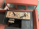
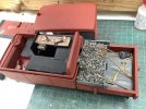
Finally this morning having added the ballast yesterday it became apparent that this would be too high at the edges so a couple more supports have been added to the sides with some seriously distressed ply and a couple of odd bits of siding as ends. Oh and the inside has some u believable plasticard made up to look like cabinets and Workbenches. It is assumed that this multi purpose trolley will be primarily used for Telephone and Wiring repairs out on the line, but any odd bits of light track-work that may come their way hence the ballast. Not seen in any of these pictures but glazing and a set of wind screen wipers have also been added.
35FBC156-AE93-4BA9-95C6-2144B35AD787.jpeg
 
In spite of the problems that are now resolved odd bits of cosmetic works have been ongoing. To hide the motor sticking out the back of the body work a ballast load has been addd, this started life as a cut out from either and LGB or Piko 4 wheeled Hopper load x the Ruschbahn as shown in the bits at the beginning if this piece. I wanted this to be removable also not gumb up the motor with glue so all the time work has been going on with this some cling film has been stuffed into the rear of the ballast load. A rear support has also been added with some thin ply and matchsticks for detail.
View attachment 271432
Next up was to use use some filler to make up the bad bits which sort of negated using the original load in the first place.
View attachment 271433
A quick spray of that when dry got it ready for the next phase, adding some real ballast.
View attachment 271434
But as can be seen above a sort of under frame has been started, this just being some 15mm deep plasticard shims held upright with further shims to keep square. The little over join is so that Incan remove the cabin and goods part separately rather than in one complete part, I feel,it important toe be able to disassemble if required.
View attachment 271435
4 20mm squares were cut and angled off at just around 6mm so that a detailed support for the wheels can be represented.
View attachment 271436
20mm ends as buffer beams have also been added in the same way as the sides using odd bits of plasticard to make the joins stronger.
View attachment 271437
Finally this morning having added the ballast yesterday it became apparent that this would be too high at the edges so a couple more supports have been added to the sides with some seriously distressed ply and a couple of odd bits of siding as ends. Oh and the inside has some u believable plasticard made up to look like cabinets and Workbenches. It is assumed that this multi purpose trolley will be primarily used for Telephone and Wiring repairs out on the line, but any odd bits of light track-work that may come their way hence the ballast. Not seen in any of these pictures but glazing and a set of wind screen wipers have also been added.
View attachment 271438
Really coming on now Jon, it's got that "economical" East German feel about it, should look at home on the DR :)
 
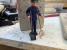
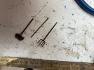
Last time out I added a pic of the inside and how it is looking to be turned into a small Workshop for line side jobs. Somewhere I think I have a kit fret with some G scale tools and hopefully a bench ....... if I can find them. But in the meantime I decided that as their is a goodly load of Ballast on the vehicle something to shovel and tamp it in place was required so I have cobbled together a Shovel and Fork. Having seen these in use in Germany they are quite different to ours the Shovel having a fairly large but shaped shovel bit with no handle on. The fork is somewhat bigger than a Garden one as well so this is my take on the two. The Shovel was made by softening a small piece of tinplate after cooking it to cherry red. This has the additional advantage of giving it a good shovel colour. Mains wire has been used for both handles with smaller wire for the forks. All soldered together. Just awaiting painting to complete except of course for the shovel bit of the shovel.
2DB6A2C5-9C95-4E61-87BB-4A15E2F83394.jpeg
There has been some detisory painting to the main unit.
CB941E76-F8F4-4739-A77D-3339ED4C7F70.jpeg
 
Been a rainy day today so some serious anal work been done.

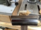
I had a look round for the Tools that I thought I had hoping for a vice, but found the sprue that at least had an Axe and Band Saw so a sort of a result. Piko and Pola also appeared less than helpful except for a very expensive workshop set that did not have a vice but some nice tools. Thus I decided to make a Vice, remembering my Grandads Workshop at Wakefield Carriage Sidings there was a big wooden vice so one of these seamed appropriate for the Workbench in Peppa. I cut up a couple of small pieces of 2mm ply which then had 3 holes drilled. Centre was 12ba screw clearance, the two others smaller around No70 for plasticard rod for the 2 guidance rods. These were only part drilled into the front plate. so that they could be glued into place. A small piece of wire was soldered onto the front of the screw head to represent the turny bit. Below you can see the parts with the reference LGB guy to show the size.
2B0522A9-6E18-4F0C-BCAF-2E202EE1EFF7.jpeg
Haing got a vice it then was time to make some sundry other tools. Bits of wire were stuck into cut cocktail sticks with very small holes drilled into them in the 60+80 drill range. A piece of plastic that has fallen off an item of rolling stock looked suitable for a couple of hammers to be cobbled from it. The spanner was made from a pice of that flat metal that keeps cardboard boxes together, yes it looks like brass but cleaned up is great for this job. The ends were filed with a fine V file then cut carefully with a junior hacksaw one end, the other with a very thin small file. Then thined in the middle with swiss files to shape. Not 100% happy with the screwdrivers but better than nowt. Oh the workbench top was distressed a little and paint pocked about again with a dab on a very fine cocktail stick, I think it is beginning to look like a used and abused workbench now.
C6DE109F-6F8D-4A7E-B6CA-E6158CB5AB0E.jpeg
Finally some more of that cardboard metal was used to make a pinch bar, a small V cut with a small swiss file, removal of the brassy colour and a slight thining out in the vice sorted the job. No self respecting railway worker would be without a pinch bar, just ask the Vicar in the Titchfield Thunderbolt.
7605D316-EAEF-4A6F-9769-5281D89AD959.jpeg
Just need to work out what the other side will have, perhaps a small cooker, newspaper, timetable etc. oh and yes the front end needs some decent controls. Have been working on an 0 Gauge Hymec so have some form on what todo here as the 0 Gauge Controls below show.
2EB9A0C2-EFA1-40EB-884F-EF18E544583F.jpeg
 
Nice job all round, the vice (or is it vise) is convincing, I'd have been none the wiser, if not for how you made it.
 
Work has been ongoing though in a modest way. One of the things that always gets me chuckling is the broom poking out of a builders transit pickup’s pole. Wanted to replicate this but first a broom! I cut a little bit of old ply from my leftovers of my Occre Tram kit. Lots of loverly offcuts sundry jobs for the use of. Found a suitable piece 5x6mm and cut a 20mm length. Shaped with a hole for a cocktail stick made the main part. The brisstles are some old string cut to short lengths and glued on with wood glue. Once dry it was then cut to shape then slopped with some thin PVA mix to get nice and solid.
70CEDA69-C01A-4339-92AF-255891C296D7.jpeg
Here you can see the completed broom with Mr.LGB for size comparison.
4E408F91-7CC2-4D53-8861-A5FB91ADC2B2.jpeg
Painted up but of course a Pway Trolley needs a Crow Bar to go with the Shovel and Fork shown previously.
AB1DC65E-6C5F-450C-AC3D-29F533305266.jpeg
This picture is a great inspiration for this project. Just wish I had seen the dossing guy enjoying the sun, that would have been a great addition.
686650CD-C902-4A64-9CD1-FF45845430A3.jpeg
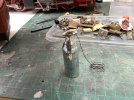
But being an avid collector of those little Gas Bottles one has been worked up to look a little like the one in the trolley. A couple of short bits of mains wire soldered to some of the thin wire makes a jib of it. All that sundry metal comes in useful with all sorts of jobs.
4979663F-4568-4306-9025-FCDDE81C3644.jpeg
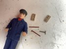
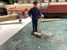
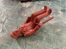
Finally for this post the Driver has been getting a Paint Over. Oh and he had to suffer an amputation to get him to fit in the seat plus have his arm looking like it was using a driving handle.
F31B10B3-FFC4-4B91-8F41-95B4147153E3.jpeg
2FFDBD34-B44C-49F6-B9F2-1482733499AD.jpeg
 
Back
Top