Bi-directional LED lighting for ancient Analog LGB loco?

viaEstrecha

Spanish metre gauge in G scale (on the cheap)
Country flag
I have an extremely ancient but loveable LGB 2051, secondhand and probably 30 years old, which is a beautiful runner, but the previous owner disconnected and mostly removed all the original lighting and so it quite literally has no lights, just some taped up wires! I would like red/white bi-directional LED lighting and possibly a cab light and so would welcome any suggestion as to how I would go about it. I'm strictly DC track-powered operation and accept the limitation that it all goes dark when the loco is stationary! I'm a dummy when it comes to electronics, so the solution has to be idiot-proof, preferably just involving attaching some self-contained LEDs without resistors and capacitors and other pieces of devil-magic, if possible. Attached the wiring diagram as-is, except that items 83, I and L are missing, with just the old wires to them from the basic circuit board remaining.
2051_wiring.png
 
I use two lead (one anode, one cathode) bi-colour LEDs (red/white) and wire them to the motor terminal through the appropriate resistor. It does mean there is no light when stationary, but quickly comes on as power is applied. As the loco changes direction the positive negative change and the alternate light comes on.
 
I agree with JimmyB, you can use two wire bi-colour LEDs for the head/tail lights. There are various sizes, I would guess you probably want a standard 3mm or 5mm type depending on the light fitting holes the loco has?

What voltage are you running up to on your DC? You'll need a suitable "devil magic" resistor as a current limiter. Some bi-colour LEDs come with a built-in resistor for running on 12V but given that we tend to run our G models at 18V - 24V you'd still need an additional resistor to handle the extra 12V.

For the cab light you could use a pair of LEDs wired inverse parallel so that one or the other lights up in either direction. You have a choice of colour such as warm white, cool white, yellow - whichever you prefer. Again a suitable resistor will be needed, and again it is possible to find LEDs with a built-in resistor for 12V but you'd still need additional resistance to limit the current draw at 24V. Alternatively you could use a grain of wheat bulb for the cab light. This will work regardless of direction. Just make sure you buy one rated for 24V, or use a pair of 12V rated bulbs wired in series.

I would probably get hold of half a dozen bi-colour LEDs (a couple of spares in case you blow one up!), half a dozen warm white LEDs (leaving 4 spares or to fit more than one pair in the cab if desired) and a bunch of 1K resistors to play with (they only cost pennies). 1K is a "safe" value used as a starting point for LEDs being powered from around 12V. You can always hook two resistors in series to allow for 24V track voltage., or just one resistor in series with one of those "12V" LEDs if that's what you end up buying. Alternatively if you know you the LEDs don't have built in resistors and you know you need to handle 24V then buy and 2K resistors from the outset.
 
Last edited:
two wire = bipolar
3 wire either common anode or common cathode with 2 leds.

sometimes the LEDs with commons work better because you can use different resistors for each LED to more carefully "tune" to the the differences between the 2 leds... i.e. sometimes you can get the LEDs to light "sooner" with a bit more fine tuning. This is especially evident between a red/white LED 1.7v vs 3.2 forward voltage drop...

Greg
Greg, these are what I bought first, but they do not work simply from the motor outputs, so went for what you have called bipolar.
 
Many thanks,, chaps. I've studied all your wise words several times, and am very grateful - I actually think I more or less understood it all and spent a couple of illuminating hours checking out components on the internet. Useful that I now also realise the difference between 2- and 3-leg LEDs and how they are used. I have enough confidence now to order in the bits and pieces to have a go. Previously I've used only LEDs with integrated resistors for scenic lighting but I reckon soldering up a single one per circuit on some strip board would be a gentle introduction to the dark arts and I'll add some other resistors to my order so I can experiment with a higher value etc: now you've whetted my appetite!

My setup uses up to 20V DC from Gaugemaster 10LGB controllers but I did the numbers based on 22V just in case and the internet calculators etc tell me this would be OK for each running lamp:
Screenshot 2021-10-20 at 08-28-23 LED Calculator - Current limiting resistor calculator for LE...png
Railway Scenics offers a 3mm 2.1v Bi-Colour Red / White LED which would be OK to install behind each running lamp aperture in place of the original clear plastic prism fitting which from the evidence of melting, was lit by a single incandescent bulb at each end of the loco. I would feed several of these in parallel from the remaining white and brown leads from the two pickup sides and will run a warm white LED also in parallel up to the cab for good measure.

If it all goes to plan, I'll complete this thread with a triumphant photo in due course!
 
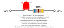
My thoughts, 30mA through a red led will be BRIGHT! Unless you have a 1 watt resistor, then this will get HOT!

Unless you’re competing with bright sunshine, 10 to 20 mA through the led should be fine.

All is not lost though, simply add another 680 ohm resistor in circuit. This will half the current, and reduce the power dissipated in each resistor by 75% ( each resistor now has half the voltage, and half the current, power is v x I so 0.5 x 0.5 is 0.25 )

Once you are happy with a simple resistor circuit, a more advanced circuit is a constant current unit. This acts like an automatic variable resistor, so at all voltages* ( and speeds ) the led is at a constant brightness.

*once the circuit has enough voltage to work, 5 or 6 volts should be enough for a red led.

A good source of leds is sets of C*******s lights, I saw some yesterday, 50 in red blue green and yellow for a couple of best British pounds!

Malcolm
Thanks, I've ordered a selection of extra resistors, as suggested, so I can experiment before fitting to judge brightness and allow for cock-ups, as this is my first attempt! Thankfully the loco has loads of space, so I'll be able to give the LEDs some clearance around them too.
 
All is not lost though, simply add another 680 ohm resistor in circuit. This will half the current, and reduce the power dissipated in each resistor by 75% ( each resistor now has half the voltage, and half the current, power is v x I so 0.5 x 0.5 is 0.25 )
This bit is slightly incorrect..
The resistors would need to be in series, so yes, each resistor would have half the voltage across it, but the same current is flowing through all the components..

PhilP
 
But because the resistance is doubled, ignoring the led volt drop, the revised circuit current is very nearly halved for the same applied voltage. So each resistor has half the voltage, and half the current, a quarter of the power
 
Have to agree with Brixham on both posts.

The rule of thumb on resistor wattage is double the calculated value.

Wattage is I squared R, or 0.03 x 0.03 x 680 which gives you 0.612 watts.... 1 watt will be hot enough to soften plastic. get a 2 watter...

I'd run the LED at 20 or even 15 ma and see if brightness is acceptable.

Also, remember no matter how high the wattage of the resistor, you are STILL putting about 2/3 of a watt into the air... a higher wattage resistor is normally larger, so the average surface temp is lower (same energy spread over a larger surface) but you are putting that much heat, 2/3 watt into the air and surroundings...

there's no magic in physics, watts is watts, they have to go somewhere...

Greg
Greg,
When I had apprentices struggling with I square R, when they were doing calculations at the bench and not using a calculator, I got them to use P=IE (for the novices E is Voltage formula is E=IxR) which helped them as it removed some of the maths when they were doing calculations at the bench and not using a calculator.
 
Yep, understand Ohms law well (taught it), but in this case we did not have the voltage drop across the resistor, only the resistance and current. That is why all permutations of Ohms law are important to remember, to substitute into the P=VI

In any case, I hope people heed the heat warning, nothing like having a hot resistor melt the side of your loco. I have a few installs that have 2 watt resistors in them.

Greg
 
As promised (threatened?), proof that the good advice was heeded and I actually managed to make it work. Took a little longer than anticipated, as I decided to repaint the LGB2051 in a slightly more Spanish livery while I had it in pieces. And then whilst the paint dried, I put lighting in an even older LGB2090 which had just dummy lights. GRS whitemetal loco lamps were put on the front and the storage bins moved 5mm outwards to allow the wiring to be concealed. Flushed with beginner's luck, I'm getting carried away and moving on to do the railcar and rolling stock lighting now and I'm no longer quite so scared of my soldering iron.
 

Attachments

  • IMG_3129.jpeg
    IMG_3129.jpeg
    975.7 KB · Views: 0
Last edited:
Back
Top