Bogie construction

JimmyB

Now retired - trains and fishing
Country flag
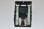
Those of you who have read my Streetcar thread will have seen I am still having problem with my power bogie, and have decided to start anew with the bogie. The plan is to make the bogie top frame from plastikard, then using the original side frames, modify one to have larger axles boxes, and then cast new side frames in polyurethane 2-part resin, the plan to then have the axles supported in (bushed) axle boxes. So has anybody used resin side frames, and are there any draw backs. I suspect the 3D printed ABS would possibly be a better, but not an option (for me), and building up from plastikard would only produce a weaker structure (imho), comments and thoughts welcome :)
 
Hmm, tricky one.

I'm not sure how much space you have, but personally, I would be tempted to make bogie sides from steel or alloy, use brass bearings, and spacer bars available from Roundhouse, then apply the detail in plastikard.

I have used Slater's Gauge 1 sprung axle boxes for compensation on one loco - it means that you have to cut a rectangular slot in the side frame, but that wouldn't be a problem for someone with your engineering background (OK, I'm a devout bodger and they work o_O ).
 
I used to produce a range of hand built slot cars. The bodies and chassis were made of vacuum molded quick cure polyurethane resin. When the chassis was mated to the body. of the same material, it formed a rigid structure that had a limited degree of flexibility, in certain parts, resulting in some degree of impact resistance. This chassis could cope with the very fast accelerating, torquey and high revving motors that I employed - up to 30,000 RPM. Here is the important bit - you need to use the right type of quick cure resin that is formulated to have a degree of impact resistance and flexibility. Some, while offering better definition for detail, are also quite brittle as a result. The driven axle on the slot car was silver steel running in phosphor bronze bearings that were snapped snug in mounts in the resin chassis. As a side issue, any exposed components were made from pewter, not straight white metal. Again impact resistance. So, if resin can work in that demanding environment then it should work in the application you propose Jimmy. Swift Sixteen produce unpowered bogies in resin but use photo etched bras to make powered ones. Max
 
Jimmy, have you looked at the Fosworks bogies - powered and unpowered? (https://fosworks.co.uk/products) I have not tried these myself but they look man enough for the job, are compensated and would take resin imitation sideframes with no problem.

Tim
 
First, many thanks for the comments, however the issue is the bogies need to be of a specific size to fit the under-frame of the Streetcar a link to the original wooden bogies post:


And a link showing the underside of the Streetcar:


So being limited on room and size, I have been unable to fine an "off the shelf" bogie that will fit, hence the need to make one myself. I would love to make the bogies out of metal, but I really do not have the facilities (or patience) any more, hence plastikard and resin castings.
 
I presume that you've looked at the Swift Sixteen extending bogie - is the problem the way the motor is mounted?

There is a guy selling gauge 1 power bogies on evilbay. They do not have insulated wheels and are slightly on the crude side, but they work
 
Nil desperandum Jimmy. The loco that has the sprung axle boxes is my 0-6-0 diesel 'Yeti' - so named when I installed the most recent gearbox and drive train ............. yetinother gearbox :rolleyes::rolleyes: the fifth, I think.

Only one of the previous four could have been described as satisfactory, and that was entirely home made using a couple of nylon gears from an old Bug Mauler. Its demise only came about when the current railroad was built and as the gearbox was made from bitsas for free while I was out of work, the gearing was too high for the gradients on this railroad.

Like the old British Rail slogan of old - we're getting there :D:D:D
 
Hmm, tricky one.

I'm not sure how much space you have, but personally, I would be tempted to make bogie sides from steel or alloy, use brass bearings, and spacer bars available from Roundhouse, then apply the detail in plastikard.

I have used Slater's Gauge 1 sprung axle boxes for compensation on one loco - it means that you have to cut a rectangular slot in the side frame, but that wouldn't be a problem for someone with your engineering background (OK, I'm a devout bodger and they work o_O ).
Good food for thought, the gear box I have is 1/8" axles and slater's are 3/16", I have tried to find a suitable gearbox at 3/16" but it seems limited. But a trawl of the interweb has found hopefully the bits I need. So the current plan is inside brass frame, delrin gear drive and cosmetic axle boxes and frames.

I presume that you've looked at the Swift Sixteen extending bogie - is the problem the way the motor is mounted?

There is a guy selling gauge 1 power bogies on evilbay. They do not have insulated wheels and are slightly on the crude side, but they work
Yes, the Swift Sixteen has a vertically mounted motor that will not fit, could not the evil seller. Just need to source some brass sheet now :)
 
How about using your existing bogie frame, with a fine saw cut down the side of the axle box, fit some suitably sized C/U channel to the axle so that it aligns with the bogie frame and it will allow the axle box to move vertically. Then drill out the axle boxes to take axle box bearings.
Theoretically you'd only need to do this to one axle to allow some compensation, or you could do this for both axles.
The current axle boxes are only 1.5 mm deep and the Slaters wheel protrude well outside, and they are only white metal so not very strong, this is why I am looking to start again, and why I considered making resin side frames. I have compensation, the issue is I only have one driven axle, and even with compensation if the weight is on the none driven axle in the bogie the driven axle slips. So part of the plan is to put delrin drive to both axles, and that take a complete redesign.
 
Spacers and hornblocks on order, I just need the material for the side frames, and I am thinking 22swg (0.80mm), initially I was thinking brass as I will be using hand tools, but would nickel silver be stronger, but is it harder to cut!!!
 
Spacers and hornblocks on order, I just need the material for the side frames, and I am thinking 22swg (0.80mm), initially I was thinking brass as I will be using hand tools, but would nickel silver be stronger, but is it harder to cut!!!
Brass will be fine possibly a bit bendy but over the length you will be using virtually irrelevant if you are careful. When drilling if you go into some sacrificial wood it will assist with the hole and stop any likely bending of the brass. Ok so drill may be blunted a little on the wood but barely noticeably so. EDIT oh just thought further and start with a smaller drill then out to size with perhaps 2 or 3 sizes to required. This helps with thin metal.
 
The current axle boxes are only 1.5 mm deep and the Slaters wheel protrude well outside, and they are only white metal so not very strong, this is why I am looking to start again, and why I considered making resin side frames. I have compensation, the issue is I only have one driven axle, and even with compensation if the weight is on the none driven axle in the bogie the driven axle slips. So part of the plan is to put delrin drive to both axles, and that take a complete redesign.
Another idea to put more weight on to the driven axle.
Using a maximum traction truck concept, have a bearing/pivot plate in place of the truck cross member with a secondary plate below this which is as close to the driven wheel as possible to transfer the maximum amount of weight on to the driven axle.

Question, if you are thinking about a delrin chain, why do you need to make a new truck. If I was to take that option I would simply put a plate/tray just below the top of the truck to carry the chain passing over the top of the axle, with sprockets just below the tray to carry the chain which passes under the axle.

Or am I missing something or thinking too simplistically?
 
Brass will be fine possibly a bit bendy but over the length you will be using virtually irrelevant if you are careful. When drilling if you go into some sacrificial wood it will assist with the hole and stop any likely bending of the brass. Ok so drill may be blunted a little on the wood but barely noticeably so. EDIT oh just thought further and start with a smaller drill then out to size with perhaps 2 or 3 sizes to required. This helps with thin metal.
Jon as you can see the frame is not very large, the bogie is just 85mm long.

Another idea to put more weight on to the driven axle.
Using a maximum traction truck concept, have a bearing/pivot plate in place of the truck cross member with a secondary plate below this which is as close to the driven wheel as possible to transfer the maximum amount of weight on to the driven axle.

Question, if you are thinking about a delrin chain, why do you need to make a new truck. If I was to take that option I would simply put a plate/tray just below the top of the truck to carry the chain passing over the top of the axle, with sprockets just below the tray to carry the chain which passes under the axle.

Or am I missing something or thinking too simplistically?
I have added 1 kg weight to the Streetcar, and there is no room for any more weight, as for the bogie, I have added as much as I can:

Streetcar_Bogie_11.jpg

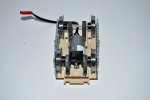
Here is a photo with the wheels and motor in place (before adding weight), as you can see no room to put the drive chain, which is why I am going for the re-design.

Streetcar_Bogie_06.jpg
 
Those collars on the axles have sort of been your nemesis for several reasons it seems.
Yeah, I think they're the insulating collars.

It's one of the scratch / bash builder's biggest nightmares over here - axle / wheel / drive gear diameter and then finding a matching gear to fit the motor shaft :rock::rock:

Doesn't make life that easy at times :shake::shake:
 
The collars have the retaining grub screw!
Yeah, and I think that's why the collars are so massive.

My Yeti is driven by Tenmille coach wheelsets, which have a resin centre and are force fitted to the axles - surprisingly, for the sort of loads that Yeti is given, this works OK
 
Back
Top