Catenary that works! Again!

James Day

Guano Corner Rly - Runs weekly - Guano permitting
Country flag
After making lots of temporary layouts with catenary that worked, I realised the other day that I had created two branches on my now 3 year old layout with catenary that didn't. Something had to be done!

I have always exploited the extra movement that catenary can bring, allowing two trains to run under independent control on the same track. I know DCC allows that, but my thing is automation and whilst I am sure automation can be done with DCC, I have no idea how to do it, or how much it would cost, nor the will to do it, wheras with a few magnets, reeds and EPL drives I can achieve a lot of movement and interaction very quickly and cheaply.

I still had a module I made 24 years ago that contained 4 EPL drives and allowed two trams to shuttle up and down a single line, passing each other in a sprung bladed loop. One tram was track powered the other catenary powered. The box had be unused for some years but that was going to be the basis for my new project.

I have a branch 67' long equipped throughout with unpowered LGB catenary. I can run trains up and down this with a shuttle module, and they can swap over at one end. I decided to power the catenary on the branch up, but my real goal is to get the twin trams operating automatically again, although that will mean adding a loop..

I no longer use EPL drives to reverse, it is horribly clumsy. A chum has built some beautiful shuttle modules for me that incorporate a variable dwell and the option to change over trains at each end. My plan was to have one module for the catenary tram, and a second for the track powered one.

So the first job was to test if two new reversing modules would operate reliably on a common return track. I set up a temporary shuttle next to one of the branches and bonded the two to form common return. The trains ran up and down on each without any issues. I could have modern smooth reversing on track and catenary with a built in dwell!

Next the 'four EPL' tram control box was dug out and everything to do with reversing was removed. This left me with two EPL drives, around half the wiring and a few switches. This was then tested and then removed from the now hopelessly big box for placing in a smaller box.

The two remaining EPLs are to be operated by the trams shuttling up and down. Each EPL relates to one track in the central passing loop. This loop has sprung points, so the trams always negotiate it the same way. As the trams arrive they switch the power to their track on and as they leave they switch it off. What stops them crashing is that the power to the isolated sections of the loop is interlocked through both EPL drives - both sections must be 'on' before either tram can leave!

The next day or two were spent installing an extra transformer and the cabling to power the catenary. It will be ready to test tomorrow. I look forward to having proper working catenary very soon!

All that remains to do then is install the loop with the sprung point blades to allow the trams to pass, wire up the revised tram control box and then I can have automated twin tram operation again for the first time in eight years!

More to follow in the next week or so.

James
 
Thank you,

Here is an image of the interlocking mechanism: Created in 1991 it was once housed in a huge box that also housed my clumsy mechanical reverser.

The two EPL drives are operated by four reeds A & C are on, B and D are off. As the trams arrive they switch the power on, but neither can leave until they are both present. As they leave they reset the system.

IMG_0647[1].jpg

The switches allow the automatic isolation to be switched, on, off or the supply to the track to be constant or nothing! The knob controls a variable resistor, like used in early LGB control huts. This allows the trams to slow before they stop. I will also link a timer into this to create a dwell before the trams move off.

Here is where the loop will go:

IMG_0648[1].jpg

At present trains and trams on the branch dwell here, but in a week or so I hope that they can pass each other instead.

IMG_0653[1].jpg

Jungle and root clearance in prsogres! The steeple cab was automatically shuttling up and down powered by the catenary! However power up was delayed, as I forgot how much voltage drop you get through my stainless steel wires. A second power mast and feed was hurriedly installed to cure this.

Sadly I have to leave it now for several days as work and other commitments take priority. Oscar Wilde was right! Work is indeed the curse....

James
 
I like the EPL system and any system that uses good old mechanical relays. Great work James.
 
Thanks Dan,

Tend to agree, although my new bespoke and expert made (not by me) reverser units are a lot better that my cobbled together EPL based ones!

This is as far as I got before work actually ceased:

IMG_0655[1].jpg

It took over 100KG of Swithland Green to fill and level that. I guess I will need a few KG more to level it properly, including under the existing track before track laying/relaying commences.

I now have a large area to build on that sort of reminds me of the FR`s cob widening.

Looking forward to getting stuck in again next week.

James
 
Hooray,

Work and stuff out the way for while at least. Back to (one of) the important things in life!

Catenary down and masts removed. Track about to be lifted

IMG_0657[1].jpg

Track removed roadbed levelled across the whole formation. New Track arrangement in place.

IMG_0659[1].jpg

Next job get the masts in, especially the tricky ones attached to the points....

James
 
At long last I have the masts in and the wires up. The isolation wiring is in too and connected the module. I have also moved the timer activation reeds to the approach to each loop.

I am using the old LGB Mk1 Catenary with set lengths of stainless steel contact wires with hooped joiners, that interlock over the masts. This means that the masts have to be in specific places. One or more mast in an arrangement like this is bound to be right next to a point.

There are a number of solutions to this. Cut the mast base back sufficiently until it just fits, or turn the arm round on the other side of the mast!! I like the latter, but use the former when I have damaged or broken mast bases. For both these methods you need an alternative fixing as the masts will no longer clip limpet like to the track.

IMG_0680[1].jpg

There are two that I use:
1 is the time honoured stake in the ground, which works well on lawns and surprisingly well in ballast! Option 2 is anchoring the mast to a flat metal plate that slides under the track. This is great for indoor layouts on floors, where screwing the masts down would be frowned upon. I have used option 2 elsewhere in the layout, but this loop needed 2 masts held by stakes driven into the Swithland Green!

So with the masts and wires up test running could commence. Just a single unit to start with, to test the workings. Sure enough there were two issues: a wire connected to the wrong place on the track and just to make it more interesting, a loose hard to trace wire in my automation box. So an hour or two wasted there!!

Trains can now shuttle up and down powered from either the catenary or the track. All I need to do now, is bring them together!

Next stop inserting four more reeds and all the wires for the automated passing in the loop.

James
 
Rain has currently stopped play, but it is always interesting to find out (again) the things that you once knew, but have forgotten.

Pre-rain test with the two trains shuttling up and down - one powered from catenary, the other from the track and me manually operating the central switches, showed up an effect I had forgotten about that one sometimes gets when using common return.

I have a timer set up to make both trams dwell in the centre, but once one tram had arrived, the arrival of the other would instantly cause them both to set off, regardless of the timer or the switches!

This only affecting the central loop isolation and not the end isolation or the shuttling, which is fine. It appears to be due to the power passing through the motor of one loco into the common return to then be picked up by the other.

I am now developing some ideas to combat this. Double isolating rails for the two central stopping points and using the timer to switch the power to the non-common rails at these sections ought to cure it, by preventing either tram to make a complete circuit until I am ready for it to do so... More to follow (when the rain stops)!
 
Pleased to say that the modification worked:

I have added double isolating rails at either side of the stopping point in each track of the loop. That in turn has the supply to the non-common rail switched through the timer, as well as the supply to the common rail.

As an insurance the supply to the common rail is also fed through two EPL drives both of which must be on, and the timer must have run out before the two trams leave!

Automation was also wired in for the centre stopping section too and I have been testing it today.

Photos and hopefully even a video? will follow soon.

James
 
Sounds great. Looking forward to a video.
 
Thanks Dan,

Video will hopefully follow soon - as a chum that is whiz with that should visit on Friday.

However, here a few images, showing the two trains shuttling up and down this afternoon.

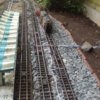
Catenary First Approach.jpg
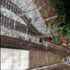
Catenart Powered Approach.jpg

Catenary Powered Train Approaching. Please excuse the red light..... but it really is coming toward you!

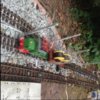
Track Powered First Approch.jpg
Track Powered Approach.jpg

The track powered train approaches (Please excuse fuzzyness on second pic)

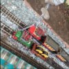
Both Trains Pause.jpg

Both trains have now paused.

Both Trains Leave.jpg

Both trains now head off to reverse and do it all again!

With hindsight, the only thing I would have done differently, would be the put the common rail on the other side. This would enable my catenary powered locos to have the hook coupling facing the other way to what it currently does, which is really what I need on this branch. It is not an impossible task to undertake, but not today, or tomorrow either come to that.

This was a pre-existing branch with the catenary in place which had been running off `track only` power since it was created. It joins end on with my other catenary equipped (but not powered) branch at a bay platform at one of my stations.

Originally the branch shown here was just a siding, which was extended and adapted, following the isolation arrangement of the other branch. When it was first built and ran off track power it didn`t matter. The other branch pushes carriages up a hill, so the locos all have hook couplings that were intended to face uphill, should the other branch ever be equipped with powered catenary, which so far it has not!

So there was careful planning and forethought, but unfortunately this turned out to be the wrong kind!

James

 
Very interesting thread James.

Just looking at the mass of wiring alongside the platform face on your last photo.

Looks awfully complex....
 
Thanks Gizzy,

I guess there are a lot of wires. It soon adds up. As I have said before, automation is my thing.

I would argue that it is all really simple, often the same basic circuit over and over again. A lot of the wiring is 'localised', but most features require a pair or two linking back to the control point.

Maybe I should have hidden it?

James
 
Before I switched to battery power and got rid of my switch machines and automated signals, I had piece-mealed all of my wiring over time. Had I a grand plan, as it seems you do, my wiring would have been organized as yours seems to be. Although my wires were buried in the ballast for the most part, I had to be careful when SWMBO wanted to do some planting.

In some respects, visible wiring, such as yours, is not only good for maintenance, but how many times have you seen cables strewn along tracks on the big "G" trains we ride on? At one point I thought of running a conduit along side the tracks, but branching off from such would be difficult at best.
 
Thanks Dan,

I like the sound of your trunking. That is what real railways do. I sometimes think of my wiring as like an overground section of London Underground!

I spent many years making temporary and indoor layouts and made up various set length colour coded leads to link things together as required in different formations. There were also 12 way distributors for automation, and ganged all the wires to the track with LGB cable clips.

When I eventually went outside long term I just followed what I had done before, although the distributors quickly suffered and were soon placed in adapted food tubs to keep the weather out.

Yes, it was all planned, but then grew and was also adapted when things were added. If I need to trace a wire, it is easy to do. I had to do this recently with my block signalling when I extended, as I had inserted another block into the system. When I need to add new wires like I did for the extension and the working catenary and loop project, they just followed the existing loom.

I have an AC block signalling 'bus' circuit and a lighting circuit with home made terminal blocks to take ring tag connections. These were made to mimic LGB 1970s connectors, but sadly will soon need a major overhaul, as they have suffered the most outside. Most track connections, including feeds to the three electrical sections are made using 'modern' LGB 10150 type double and single isolating rails.

Apart from a handful of recent issues with the lighting circuit, I have had virtually no wiring related failures since I overhauled and enclosed the distributors. Fingers crossed that my luck holds!

James
 
Good weather yesterday,

A knowledgeable chum came round and we ran lots of trains. There was some filming done too, with a video to follow.

The running of multiple trains did show up a drawback with my planning for the shuttle: The system is dependant on several timers, but there is no link between them. Whilst it is left alone to get on with it, it generally works well, but.......generally is not quite good enough.

The report card says more work is needed!

The timers on the track powered and catenary powered shuttles are set the same. The third timer is on the central dwell, which activates when either tram enters the loop, to stop them both leaving with indecent haste. However, just 'north' of the passing loop there is a junction where the shuttle trains cross the mainline. Often shuttle trains have to wait, especially if there are lots of trains on the mainline, like there were yesterday - We had 6 running.

This tended to throw the shuttle timers out of sync, and often meant that a train would 'time out' and reverse whilst waiting to be passed.

The shuttle timers are activated by a lack of current being drawn, and the moment that current starts being drawn again they go back to zero. If no current is drawn for the set time, the timer reverses the power. At present we have the timers set to around two minutes, although we could go longer.

The real solution appears to be switching in an alternative thing to draw current, whilst the shuttle train is waiting to be passed. A bulb would do it, so that is the plan. As soon as the rain stops and I can get out there with my soldering iron, I will try out installing a 'waiting load' on both traction supplies and see what happens!

I think Robert the Bruce must have had automated LGB.

James
 
It did stop raining briefly and I was able to try out the 'waiting load' concept and it worked, (both timers stopped) but it also illustrated that it is impossible to differentiate between which tram it is that is waiting to be passed, and which is waiting to reverse without a system to do this.

Ironically I did have a system that did this 24 years ago, with detectors mounted on one side of the track for switching the track powered tram and the other side for switching the catenary powered one. My two LGB trams still have old Tri-ang X04 motor magnets stuck under their skirts to activate these!

I had hoped that using modern voltage sensing shuttle modules would do away with the need for detection and It has to be conceded that for simple operation they 'almost' do, but the added complication of the crossing of the main line and the uncertain lengths of the delays this can cause means I need to go back to the future.

I no longer have a source of old X04 magnets and they are little bulky and weak for what I am trying to do, so 50 of 5 x 5 x 5 mm super-neo magnets have just been ordered.

To be continued....

In full Robert the Bruce mode now......
 
A quick and dirty video here....

https://www.youtube.com/watch?v=aP_E5UoR5OE


Raw camera footage....no edits....

Malcolm
 
Thanks Malcolm,

The video clip shows the branch where is crosses the main line, as well as the passing loop.

Trains on the branch can be seen passing each other and waiting to cross the main line.

When Malcolm shot this the timers were all working together and the trains shuttled up and down and passed as they should.

What the video does not show is when trains 'time out' and either reverse before they cross the mainline, or time out and end up beached in the loop. The delays and timing out are all caused by the volume of traffic on the main line.

A solution is being prepared involving 'train describing' magnets mounted on one side or the other of the train and home made reeds at the track side. These will activate an EPL drive that switches on a 'waiting load' bulb whilst the train traverses the central section. The current drawn by the bulb fools the timer into thinking that this train is still running when it may actually be waiting and the timer will only reverse once the train is clear of the loop and junction and really has reached the end of the line.

There is a separate set of reeds, an EPL and a bulb for each train, triggered only by the magnets at the appropriate side of each train.

Preparation for installing this continues.......

Still trying and hoping to succeed!

James
 
James, that is fantastic !! The number of trains you have running would keep anyone's attention for quite some time. Kudos to you and your equipment.
 
Back
Top