David1226
Registered
Part 1 of 3
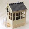
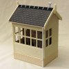
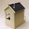
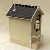
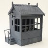
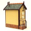
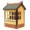
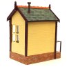
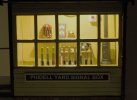
The layout for the Claptowte Railway was constructed as a means of displaying the rolling stock, which is unique, with every item having been ‘kit bashed’ so that nothing is as purchased. For that reason the fiddle yard, appropriately named Phidell Yard, is fully open to view, rather than being concealed, with the stock hidden away. Having already acquired a water tower, water crane and locomotive coaling stage, to ‘decorate’ the yard, I decided the yard also needed signal box.
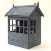
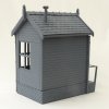
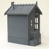
I purchased a cast resin kit of a brick based low level wooden signal box from Modeltown. The model is designed so that the assembled walls and roof are a loose fit over the base, to give access to the interior of the box.
Below is a view of the parts supplied with the kit, after they have been sanded and filed to remove any flash. I also ran the side of a razor saw over the planking, to impart some wood grain, but this is very subtle and I’m not sure that it will show through the paint finish. Everything was then washed. Glazing material is also supplied in the kit.
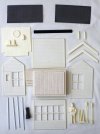
As I wanted to add extra detail, and lighting, to the interior, I went about assembling the kit in a different way to that described in the instructions supplied. I did not use the three items shown in the bottom right of the picture. The signalman figure, although nicely moulded, was slightly over scale, and not as life like as the other figures that I have (G Scale Bachmann). The ‘signal levers’ are a very crude representation and were replaced. For Gernise End Signal Box, I scratch built the lever frame, not wishing to spend the time going down that route again, I purchased some excellent 3D printed items, from eBay, as described later. The pair of items, extreme bottom right, are brackets, designed to hold the walls of the signal cabin to the base, and for my construction, are redundant.
The four white plastic strips, bottom left, are right-angle strips intended to glue to the four vertical corners of the cabin. I decided to omit these from my model.
It was my intention to glue the cabin walls to the base, and to alter the roof, to make that removable instead. As the cabin would be a very loose fit over the base, and would need packing out, I started construction by gluing together the four sides of the cabin. I could then place the cabin over the base, to see how much I would need to fill out the sides of the base for a snug fit.
The cabin walls glued together
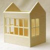
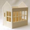
Having assembled the cabin walls, they were placed over the base to see how much fill-in was required between the walls and the cabin floor.
A view of the unmodified base.
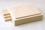
A view of the underside of the cabin base before it was modified
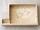
The gaps were filled in using various thicknesses of plastic strip, 4.0mm high, the height difference between the top of the brick base wall and the cabin floor.
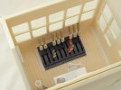
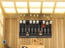
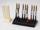
At this point, I should show the lever frame that is to be installed, in place of the one supplied with the kit. It is actually two sets of a 3D printed five lever frames, joined together to make a ten lever frame. I pre-painted the lever frame before assembly.
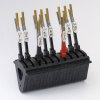
As can be seen, the lever frame extends below floor level, which requires a rectangular hole to be cut into the floor of the signal cabin, in order to accommodate the mechanism.
A view of the 3D printed frame, beside the levers supplied in the kit.
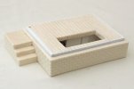
Here is the modified base.
The plastic strips have been glued on to expand the cabin floor to be a snug fit to the walls when they are glued on. The slot has been cut out, in the floor, to accommodate the signal lever frame. The hole drilled, at the rear left corner of the floor, is to allow for the connection of the lights to the battery pack now installed on the underside of the base.
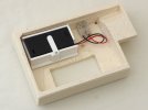
Here is a view of the underside of the modified base.
I constructed a cradle, from 3.0mm plasticard, to hold a 2 x AA switchable battery box, to supply the 3V LED lights. The moveable arm holds the battery box in place, it can removed to change the batteries. This is the same set up that I have used to light my other buildings. The wires from the lights will entre via the hole in the corner and be connected into the terminal block.
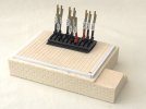
The base with the lever frame temporarily in position
The kit comes with an interior back wall, to be glued into the rear of the cabin. This wall is slightly narrower, in width, than the than the interior of the modified base. By positioning this wall tight to the right of the interior, it leaves a gap down the left hand side. This gap was covered by a strip of thin plasticard. When the interior wall is glued in place, this creates a vertical void, down which the wiring from the lamps can be passed, and thus, through the hole drilled in the base, to the battery pack in the base.
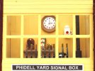
The moulded ‘detail’ on the interior wall is quite rudimentary and crudely moulded. There is a clock, for which a printed clock face is supplied. There is a shelf with two featureless items moulded on. The left hand item has the distinctive rounded top that would suggest it is intended to be a token machine. The item to its right I assume to be a representation of a block instrument. There is also a representation of a hand signalling lamp. I decided to tackle these mouldings, to add some extra detail.
While the design of tokens can differ in appearance, the token machines all have a similar and distinctive appearance. I started by carving out the distinctive pattern of slots, into which the tokens are inserted, on the face of the machine. I added a few bits and bobs to represent the various knobs and dials on the machine. I rounded off the ends of some short lengths of handrail wire to represent tokens inserted into the machine.
I added some plasticard details to the front of the block instrument, to represent switches.
I used a shaped offcut of plasticard to extend the length of the moulded shelf, by about 7mm, in order to accommodate a signalling bell to the right of the block instrument. The bell cabinet work is plasticard offcuts glued together, and the bell, itself, is a brass plated upholstery nail, the same method that I used to scratch build the signal bells in the Gernise End Signal box.
Finally, I carved off the horribly oversized handle on the hand signal lamp, and replaced it with a brass wire handle.
The wall detail before alteration

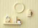
The wall detail after alteration. After I had taken this photo, I decided that the lamp still looked too bulky, so a cut 3.5mm off the bottom of the body, to reduce its size.
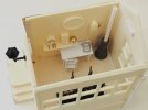
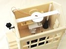
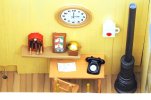
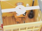
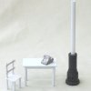
The other detail that I added to the interior is a scratch built plasticard table and chair. A white metal telephone, from Pendle Valley Models. I added a plastic tube flue pipe to the top of the resin cast stove, supplied with the kit.
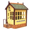
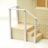
For the exterior of the signal box, I added posts and railings for the entrance steps. For the purpose of this photo, and until painted and glued on, they are held together with blobs of bluetac.
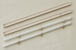
The kit did not come with any guttering and rain water down pipes, so I had to construct these myself. I sourced some suitably sized half round plastic channel for the guttering and blanked off the ends with plasticard sheet. The down pipes were constructed from various thicknesses of plastic tube.
David
The layout for the Claptowte Railway was constructed as a means of displaying the rolling stock, which is unique, with every item having been ‘kit bashed’ so that nothing is as purchased. For that reason the fiddle yard, appropriately named Phidell Yard, is fully open to view, rather than being concealed, with the stock hidden away. Having already acquired a water tower, water crane and locomotive coaling stage, to ‘decorate’ the yard, I decided the yard also needed signal box.
I purchased a cast resin kit of a brick based low level wooden signal box from Modeltown. The model is designed so that the assembled walls and roof are a loose fit over the base, to give access to the interior of the box.
Below is a view of the parts supplied with the kit, after they have been sanded and filed to remove any flash. I also ran the side of a razor saw over the planking, to impart some wood grain, but this is very subtle and I’m not sure that it will show through the paint finish. Everything was then washed. Glazing material is also supplied in the kit.

As I wanted to add extra detail, and lighting, to the interior, I went about assembling the kit in a different way to that described in the instructions supplied. I did not use the three items shown in the bottom right of the picture. The signalman figure, although nicely moulded, was slightly over scale, and not as life like as the other figures that I have (G Scale Bachmann). The ‘signal levers’ are a very crude representation and were replaced. For Gernise End Signal Box, I scratch built the lever frame, not wishing to spend the time going down that route again, I purchased some excellent 3D printed items, from eBay, as described later. The pair of items, extreme bottom right, are brackets, designed to hold the walls of the signal cabin to the base, and for my construction, are redundant.
The four white plastic strips, bottom left, are right-angle strips intended to glue to the four vertical corners of the cabin. I decided to omit these from my model.
It was my intention to glue the cabin walls to the base, and to alter the roof, to make that removable instead. As the cabin would be a very loose fit over the base, and would need packing out, I started construction by gluing together the four sides of the cabin. I could then place the cabin over the base, to see how much I would need to fill out the sides of the base for a snug fit.
The cabin walls glued together


Having assembled the cabin walls, they were placed over the base to see how much fill-in was required between the walls and the cabin floor.
A view of the unmodified base.

A view of the underside of the cabin base before it was modified

The gaps were filled in using various thicknesses of plastic strip, 4.0mm high, the height difference between the top of the brick base wall and the cabin floor.
At this point, I should show the lever frame that is to be installed, in place of the one supplied with the kit. It is actually two sets of a 3D printed five lever frames, joined together to make a ten lever frame. I pre-painted the lever frame before assembly.

As can be seen, the lever frame extends below floor level, which requires a rectangular hole to be cut into the floor of the signal cabin, in order to accommodate the mechanism.
A view of the 3D printed frame, beside the levers supplied in the kit.

Here is the modified base.
The plastic strips have been glued on to expand the cabin floor to be a snug fit to the walls when they are glued on. The slot has been cut out, in the floor, to accommodate the signal lever frame. The hole drilled, at the rear left corner of the floor, is to allow for the connection of the lights to the battery pack now installed on the underside of the base.

Here is a view of the underside of the modified base.
I constructed a cradle, from 3.0mm plasticard, to hold a 2 x AA switchable battery box, to supply the 3V LED lights. The moveable arm holds the battery box in place, it can removed to change the batteries. This is the same set up that I have used to light my other buildings. The wires from the lights will entre via the hole in the corner and be connected into the terminal block.

The base with the lever frame temporarily in position

The kit comes with an interior back wall, to be glued into the rear of the cabin. This wall is slightly narrower, in width, than the than the interior of the modified base. By positioning this wall tight to the right of the interior, it leaves a gap down the left hand side. This gap was covered by a strip of thin plasticard. When the interior wall is glued in place, this creates a vertical void, down which the wiring from the lamps can be passed, and thus, through the hole drilled in the base, to the battery pack in the base.
The moulded ‘detail’ on the interior wall is quite rudimentary and crudely moulded. There is a clock, for which a printed clock face is supplied. There is a shelf with two featureless items moulded on. The left hand item has the distinctive rounded top that would suggest it is intended to be a token machine. The item to its right I assume to be a representation of a block instrument. There is also a representation of a hand signalling lamp. I decided to tackle these mouldings, to add some extra detail.
While the design of tokens can differ in appearance, the token machines all have a similar and distinctive appearance. I started by carving out the distinctive pattern of slots, into which the tokens are inserted, on the face of the machine. I added a few bits and bobs to represent the various knobs and dials on the machine. I rounded off the ends of some short lengths of handrail wire to represent tokens inserted into the machine.
I added some plasticard details to the front of the block instrument, to represent switches.
I used a shaped offcut of plasticard to extend the length of the moulded shelf, by about 7mm, in order to accommodate a signalling bell to the right of the block instrument. The bell cabinet work is plasticard offcuts glued together, and the bell, itself, is a brass plated upholstery nail, the same method that I used to scratch build the signal bells in the Gernise End Signal box.
Finally, I carved off the horribly oversized handle on the hand signal lamp, and replaced it with a brass wire handle.
The wall detail before alteration

The wall detail after alteration. After I had taken this photo, I decided that the lamp still looked too bulky, so a cut 3.5mm off the bottom of the body, to reduce its size.

The other detail that I added to the interior is a scratch built plasticard table and chair. A white metal telephone, from Pendle Valley Models. I added a plastic tube flue pipe to the top of the resin cast stove, supplied with the kit.

For the exterior of the signal box, I added posts and railings for the entrance steps. For the purpose of this photo, and until painted and glued on, they are held together with blobs of bluetac.

The kit did not come with any guttering and rain water down pipes, so I had to construct these myself. I sourced some suitably sized half round plastic channel for the guttering and blanked off the ends with plasticard sheet. The down pipes were constructed from various thicknesses of plastic tube.

David
Last edited:

