David1226
Registered
Part 1 of 4
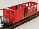
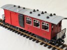
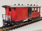
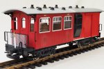
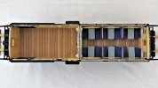
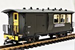
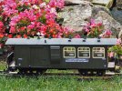
When assembling the fleet of passenger vehicles for the Claptowte Railway, I was always collecting to a plan. Okay, that plan changed over the years, to accommodate new ideas, but there was always a plan. The object was to portray a piecemeal collection of narrow gauge bogie coaches, of differing designs, from differing sources, but all with the same corporate livery and identity.
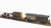
Although the number of vehicles per passenger rake has increased from three to four, there are still, as originally intended, four rakes of locomotive hauled coaches. The designs included four brake/third and one full brake coach. This means that there would always have been a spare brake vehicle. The premise was always going to be, right from the start, even before the majority of coaches had been built, that one of the brake/third coaches was going to be withdrawn from passenger revenue service to be converted into a mess/tool van to accompany the company’s mobile crane, even though the parts to build the crane had yet to be purchased. The ‘converted’ coach would be re-livered in Engineering Department green.
The fleet of Claptowte Railway coaches are numbered 1 – 18, although they were never built in that order, however, there are only seventeen of them. Coach No3 was always missing, destined to be the Engineering Department Tool/Mess Van.
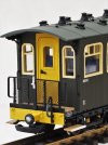
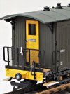
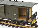
Coach No3 was intended to be the twin of coach No4, made from joining a LGB Toy Train 4-wheel coach and a balcony van, and mounting them on LGB Jackson Sharp bogies. Coach No4 was one of the very first coaches that I built for the Claptowte Railway, and the first that I built by grafting together two 4-wheel vehicles from the LGB Toy Train range.
The joining together of two 4-wheel Toy Train coaches, to make a bogie coach, is a path taken by many before me. What I had not previously seen, when I embarked on this project back in 2006, was the joining together of a 4-wheel coach and a balcony ended van, to make a brake coach. Wishing to produce something different to the rest, I decided to start with this conversion. No sooner had I started, I realised why no one had attempted it before, both the body height and the roof profile of the donor vehicles are different. The rectification of these problems entailed quite a bit of extra work to the van body and its roof profile. Having done this, I had to create a curved roof to run the full length of the new combined bodies. I used 2.0mm plastic sheet, the curving of which involved much swearing, blaspheming and throwing of tools out of windows. These were not processes that I was in a hurry to repeat, and explains why I left the building of the twin vehicle to the very last, after I had built all the rest of the coaches.
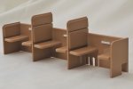
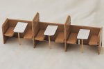
So here we are, over sixteen years later, and sixteen coach builds/modifications, in between, it’s time to build the twin of coach No4. Well not an exact twin, over the years, with other builds, I have practiced, and in some areas, refined my modelling techniques. There are some subtle differences between the two builds. The most obvious physical difference is the roof. Whereas No4 has a one-piece plasticard roof, with No3, after all of my previous conversions, I ended up with a spare 4-wheel coach roof, so the roof for No4 was created by joining two 4-wheel roofs together. This created extra work, but of a different kind which I will explain as I go along. The other alteration is the addition of tables in the passenger compartment, to create a mess room for the Engineering Department staff.
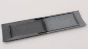
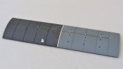
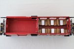
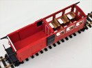
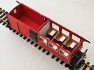
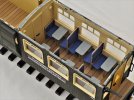
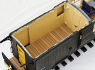
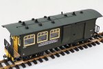
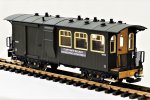
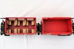
The photos below show the donor vehicles before any modifications were carried out
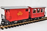
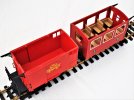
For this build, I decided it would be easier to carry out the modifications to each of the body shells before joining them together. I started with the passenger coach body. I have identified each alteration with a letter.
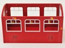
A The moulded rib at the end of the body, where it will be joined, carved off and sanded smooth, both sides.
B Retaining slots, for the roof fixing taps, filled in with thin plasticard, flush with the outer surface, so that tabs still fit into slots on inner surface.
C Windows framed with 2.0 x 1.5mm plastic strip.
D Interior of end wall sheeted over with 0.5mm plasticard to cover window aperture
E Dummy door frame from plasticard strip.
F Bent brass wire door handle.
G Holes drilled to line up with van body, so that the two bodies can be bolted together with 4.0mm bolts, so reinforce glue.
H Slots to facilitate reinforcing brass strips where roof sections joined.
Alterations to body of Toy Train balcony ended van
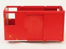
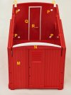
I The moulded rib at the end of the body, where it will be joined, carved off and sanded smooth, both sides.
J The window aperture, on each side, enlarged to facilitate guards ducket.
K Raised moulded panel, on each side, carved off and sanded flush with body side, then scribed to replicate planking.
L 3.0mm deep plasticard strip glued to bottom edge to make up wall height to match coach body, scribed to replicated planking.
M Moulded pipe work and valve, on end wall, carved off, sanded flush and scribed to replicate planking.
N Plasticard, made up to thickness of end wall, carved and sanded to shape to match roof profile of passenger coach
O Slots to facilitate reinforcing brass strips where roof sections joined.
P Holes drilled to line up with coach body, so that the two bodies can be bolted together with 4.0mm bolts, so reinforce glue.
Q Dummy door frame from plasticard strip.
R Bent brass wire door handle.
That completed the alterations to the two bodies. Before gluing them together, I packed out the void spaces between the two body backs by gluing in offcuts of platicard, to bring the two surfaces of the bodies flush. After gluing the two bodies together, I inserted four bolts through the pre-drilled holes, to reinforce the join.
After the bodies were joined, the join was smoothed out and the planking re-scribed. Last of all, a pair of Garden Railway Specialists (GRS) guards duckets were glued on, over the enlarged apertures on the side of the van body.
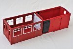
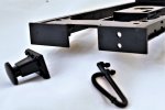
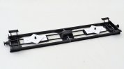
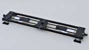
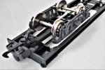
I decided to build the coach body before tackling the underframe and the roof. I knew there would be a small gap to be made up between the two 4-wheeler underframes, and, until they could be offered up to the completed body, there was no way to determine how wide that gap would be. For the same reason, the roof was left as a small amount would have to be cut off the length of each roof section, before they could be joined.
David
When assembling the fleet of passenger vehicles for the Claptowte Railway, I was always collecting to a plan. Okay, that plan changed over the years, to accommodate new ideas, but there was always a plan. The object was to portray a piecemeal collection of narrow gauge bogie coaches, of differing designs, from differing sources, but all with the same corporate livery and identity.
Although the number of vehicles per passenger rake has increased from three to four, there are still, as originally intended, four rakes of locomotive hauled coaches. The designs included four brake/third and one full brake coach. This means that there would always have been a spare brake vehicle. The premise was always going to be, right from the start, even before the majority of coaches had been built, that one of the brake/third coaches was going to be withdrawn from passenger revenue service to be converted into a mess/tool van to accompany the company’s mobile crane, even though the parts to build the crane had yet to be purchased. The ‘converted’ coach would be re-livered in Engineering Department green.
The fleet of Claptowte Railway coaches are numbered 1 – 18, although they were never built in that order, however, there are only seventeen of them. Coach No3 was always missing, destined to be the Engineering Department Tool/Mess Van.
Coach No3 was intended to be the twin of coach No4, made from joining a LGB Toy Train 4-wheel coach and a balcony van, and mounting them on LGB Jackson Sharp bogies. Coach No4 was one of the very first coaches that I built for the Claptowte Railway, and the first that I built by grafting together two 4-wheel vehicles from the LGB Toy Train range.
The joining together of two 4-wheel Toy Train coaches, to make a bogie coach, is a path taken by many before me. What I had not previously seen, when I embarked on this project back in 2006, was the joining together of a 4-wheel coach and a balcony ended van, to make a brake coach. Wishing to produce something different to the rest, I decided to start with this conversion. No sooner had I started, I realised why no one had attempted it before, both the body height and the roof profile of the donor vehicles are different. The rectification of these problems entailed quite a bit of extra work to the van body and its roof profile. Having done this, I had to create a curved roof to run the full length of the new combined bodies. I used 2.0mm plastic sheet, the curving of which involved much swearing, blaspheming and throwing of tools out of windows. These were not processes that I was in a hurry to repeat, and explains why I left the building of the twin vehicle to the very last, after I had built all the rest of the coaches.
So here we are, over sixteen years later, and sixteen coach builds/modifications, in between, it’s time to build the twin of coach No4. Well not an exact twin, over the years, with other builds, I have practiced, and in some areas, refined my modelling techniques. There are some subtle differences between the two builds. The most obvious physical difference is the roof. Whereas No4 has a one-piece plasticard roof, with No3, after all of my previous conversions, I ended up with a spare 4-wheel coach roof, so the roof for No4 was created by joining two 4-wheel roofs together. This created extra work, but of a different kind which I will explain as I go along. The other alteration is the addition of tables in the passenger compartment, to create a mess room for the Engineering Department staff.
The photos below show the donor vehicles before any modifications were carried out


For this build, I decided it would be easier to carry out the modifications to each of the body shells before joining them together. I started with the passenger coach body. I have identified each alteration with a letter.

A The moulded rib at the end of the body, where it will be joined, carved off and sanded smooth, both sides.
B Retaining slots, for the roof fixing taps, filled in with thin plasticard, flush with the outer surface, so that tabs still fit into slots on inner surface.
C Windows framed with 2.0 x 1.5mm plastic strip.
D Interior of end wall sheeted over with 0.5mm plasticard to cover window aperture
E Dummy door frame from plasticard strip.
F Bent brass wire door handle.
G Holes drilled to line up with van body, so that the two bodies can be bolted together with 4.0mm bolts, so reinforce glue.
H Slots to facilitate reinforcing brass strips where roof sections joined.
Alterations to body of Toy Train balcony ended van


I The moulded rib at the end of the body, where it will be joined, carved off and sanded smooth, both sides.
J The window aperture, on each side, enlarged to facilitate guards ducket.
K Raised moulded panel, on each side, carved off and sanded flush with body side, then scribed to replicate planking.
L 3.0mm deep plasticard strip glued to bottom edge to make up wall height to match coach body, scribed to replicated planking.
M Moulded pipe work and valve, on end wall, carved off, sanded flush and scribed to replicate planking.
N Plasticard, made up to thickness of end wall, carved and sanded to shape to match roof profile of passenger coach
O Slots to facilitate reinforcing brass strips where roof sections joined.
P Holes drilled to line up with coach body, so that the two bodies can be bolted together with 4.0mm bolts, so reinforce glue.
Q Dummy door frame from plasticard strip.
R Bent brass wire door handle.
That completed the alterations to the two bodies. Before gluing them together, I packed out the void spaces between the two body backs by gluing in offcuts of platicard, to bring the two surfaces of the bodies flush. After gluing the two bodies together, I inserted four bolts through the pre-drilled holes, to reinforce the join.
After the bodies were joined, the join was smoothed out and the planking re-scribed. Last of all, a pair of Garden Railway Specialists (GRS) guards duckets were glued on, over the enlarged apertures on the side of the van body.

I decided to build the coach body before tackling the underframe and the roof. I knew there would be a small gap to be made up between the two 4-wheeler underframes, and, until they could be offered up to the completed body, there was no way to determine how wide that gap would be. For the same reason, the roof was left as a small amount would have to be cut off the length of each roof section, before they could be joined.
David
Last edited:

