David1226
Registered
When originally conceived, as an end to end layout, Gernise End Station on the Claptowte Railway had a requirement for six signals. There was never a need for the signals to be lit or to operate in a prototypical manner, they were always intended to be scenic items. As a result, I settled on the cheapest, most basic G Scale signals on offer, produced by Modeltown in their Easy Build Kit range. Thus six were purchased some time ago and put to one side. As I said the design was quite basic and did not include a ladder, so that was something I had to source myself. The ladders available commercially, either brass or plastic, each cost almost as much as the original signal kit, so I embarked on making my own
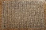
To make my own ladders I bought a sheet of 1/2” square wire mesh, cut strips from it, filled the sides, then cut the strips to length to create ladders.
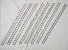
When the track plan for the Claptowte Railway was redesigned as an oval, there was a need for four additional signals. At the time the Modeltown signal was out of stock and when they became available they were of a different design, which this time, did include a ladder. The ladder supplied was identical to those I had made myself.
The design differences between the two types were mostly to the signal base. I had a careful look at the two different base designs and decided that both could be modified in such a way that they could be made to look very similar, thus I could end up with ten virtually identical signals. My requirement was for 4 X Home signals; 2 X Distant signals and 4 x Home/Distant signals. The different signal arms were included in both kits. The kits also included 6mm jewels, in red and green, to represent the lamps on the home signal, but there was no yellow jewel to represent the caution lamp on the distant signal. Also, although alternative signal arms were included, the kit only contains one green jewel, so if using both arms to create a Home/Distant signal, you also need to acquire an additional green jewel. To overcome this I bought some 6mm yellow and green jewels from Ebay.
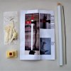
The picture below shows the earlier, original design of Modeltown signal. The finial is made up from a metal bead and a pop rivet, crude but effective. The base is quite small in area and the signal lever attaches directly to the front of the post support.
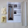
The next picture shows the latest version of the Modletown Easy Build Signal Kit. The finial is now a resin casting, the base is much larger, with the signal lever now fitted into its own support brackets, and, as previously stated, ladder is now included in the kit.
Here are the two signal bases side by side, the old design on the left, the new design, on the right. I have included the signal arms and signal levers so that you can see the orientation of the bases.
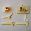
Here are the two bases after I have modified them. The footprint of the old signal has been enlarged by a piece of plasticard glued to it. A thinner piece of plasticard has been glued over the bottom surface of the enlarged base to add reinforcement. The larger base allows for the foot of the ladder to be placed away from the bottom of the post to give a less acute climbing angle. I drilled two holes in each base to locate the bottom of the ladders. For consistency I made up a couple of templates for the positioning of the holes.
The newer design has been altered by cutting off the signal lever brackets and the lip where it was intended that the foot of the ladder should be fitted. The whole base is then rotated by 90 degrees so that again the foot of the ladder can be moved further away from the signal post, to reduce the angle. The base that holds the post has been drilled so that, as with the original design, the signal lever can be attached to the base of the post. . Again, I have included the signal arms and levers so that the new orientations of the bases can be seen
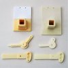
The next job was to tackle the signal posts. These are made up of a length of square section plastic tube with a snug fitting wooden core. All of the posts were of slightly different lengths so all were cut to the length of the shortest post to end up with ten posts of equal height. As the posts are supposedly made of timber, I have added some wood grain by my usual technique of drawing the teeth of a razor saw along their length.
The instruction sheet for the old style of kit suggests that you file and sand the top of the post into a dome shape. A hole is then drilled down the centre into which is glued the tail of the pop rivet and bead that forms the finial. I did not want to go to the performance of shaping the tops. The finials supplied with the updated kit are resin castings that have a flat base. Instead of filing the tops of the posts, I capped them with a square of 3mm thick plasticard and drilled a hole down the centre of that. The bead and pop rivet were then glued into the capped end. Although dimensionally different, the old and the new style finials are similar in appearance, and as no two signal posts will be standing next to each other, as with the bases, the differences are hardly noticeable. I actually mixed and matched some of the old/new finials/bases to further enhance the uniformity.
Prior to assembly, all of the various components were painted, starting with a coat of grey plastic primer. The exception to this was the signal posts which were left in their unpainted white plastic. The finials on the Home and Home/Distant signals were painted signal red and those on the Distant signals, signal yellow. The signal post bases where masked up and sprayed satin black, then the bases were painted as weathered concrete.
With regard to the semaphore arms, they are identical in both kits. I masked off the semaphore blade and sprayed the counter weight satin black. I then reversed the process and sprayed the semaphore blade satin white. The white gave a good undercoat for the signal red and signal yellow overpainting. I stuck on a 5mm wide strip of electrical tape in the position of the white vertical stripe on the face of the Home semaphores. After painting the faces in signal red, this was then peeled off to reveal a perfect white stripe on the signal. I stuck on a 5mm wide strip of black electrical tape vertically on the white reverse of the signal arm to complete it. The black chevron stripes on the front and rear of the Distant signal were cut from electrical tape and stuck on. These were cut by eye and as such not all were the same thickness, but again, as no two will be standing next to each other, this will not notice.
As shown in the instruction sheets, the kits assemble into lower quadrant signal. By adjusting the position of the operating lever and wire, I converted mine to operate as upper quadrant signals. I drilled a small hole beneath each operating semaphore arm and glued in a short length of operating wire to create a stop peg that prevents the signal from dropping below the horizontal. This applies to the semaphore arms on the Home and Distant signals and upper arm of the Home/Distant signals. With the Home/Distant signals, I did not require the Distant semaphore to move as in practicable terms these would be fixed distants anyway, for that reason they were just glued onto the signal post in the caution position.
Having assembled the base, post, semaphore arms, levers, control wires, and finials, next came the ladders. Combining my home made ladders with those supplied in the updated kits, once they were cut to length and bent to shape, I ended up with ten identical ladders. Having glued them in place, I decided that they really needed some support stays to secure them to the posts. I created these with strips of 1.5. x 2.0mm plastic strip, with 1mm self adhesive pearl jewels as bolt heads. The final touch was to add a few tufts of 4mm grass growing through cracks in the concrete base.
As I stated previously, I did not need the signals to operate but I did want the area to be correctly signalled. The way in which the layout is operated means that, in practical terms, all of the distant signals would be fixed distants, so would not need to move anyway. The intention is that the signals can be placed onto a flat basebord and lightly held in place with a couple of blobs of Blutack in order to facilitate easy removal. While there are more detailed operating and lit semaphore signal kits available, at considerably more expense, I am very happy with the appearance of these signals. They fully meet my criteria, as purely scenic items, and I believe that my alterations to the kits have lifted the appearance of the finished model.
Here are the two Distant signals
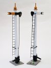
Here are the four Home signals
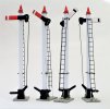
Here are the four Home/Distant signals
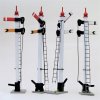
Here are all three signal types
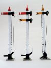
Here is the full complement of ten signals for the Claptowte Railway
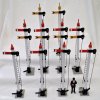
David
To make my own ladders I bought a sheet of 1/2” square wire mesh, cut strips from it, filled the sides, then cut the strips to length to create ladders.


When the track plan for the Claptowte Railway was redesigned as an oval, there was a need for four additional signals. At the time the Modeltown signal was out of stock and when they became available they were of a different design, which this time, did include a ladder. The ladder supplied was identical to those I had made myself.
The design differences between the two types were mostly to the signal base. I had a careful look at the two different base designs and decided that both could be modified in such a way that they could be made to look very similar, thus I could end up with ten virtually identical signals. My requirement was for 4 X Home signals; 2 X Distant signals and 4 x Home/Distant signals. The different signal arms were included in both kits. The kits also included 6mm jewels, in red and green, to represent the lamps on the home signal, but there was no yellow jewel to represent the caution lamp on the distant signal. Also, although alternative signal arms were included, the kit only contains one green jewel, so if using both arms to create a Home/Distant signal, you also need to acquire an additional green jewel. To overcome this I bought some 6mm yellow and green jewels from Ebay.
The picture below shows the earlier, original design of Modeltown signal. The finial is made up from a metal bead and a pop rivet, crude but effective. The base is quite small in area and the signal lever attaches directly to the front of the post support.

The next picture shows the latest version of the Modletown Easy Build Signal Kit. The finial is now a resin casting, the base is much larger, with the signal lever now fitted into its own support brackets, and, as previously stated, ladder is now included in the kit.

Here are the two signal bases side by side, the old design on the left, the new design, on the right. I have included the signal arms and signal levers so that you can see the orientation of the bases.

Here are the two bases after I have modified them. The footprint of the old signal has been enlarged by a piece of plasticard glued to it. A thinner piece of plasticard has been glued over the bottom surface of the enlarged base to add reinforcement. The larger base allows for the foot of the ladder to be placed away from the bottom of the post to give a less acute climbing angle. I drilled two holes in each base to locate the bottom of the ladders. For consistency I made up a couple of templates for the positioning of the holes.
The newer design has been altered by cutting off the signal lever brackets and the lip where it was intended that the foot of the ladder should be fitted. The whole base is then rotated by 90 degrees so that again the foot of the ladder can be moved further away from the signal post, to reduce the angle. The base that holds the post has been drilled so that, as with the original design, the signal lever can be attached to the base of the post. . Again, I have included the signal arms and levers so that the new orientations of the bases can be seen

The next job was to tackle the signal posts. These are made up of a length of square section plastic tube with a snug fitting wooden core. All of the posts were of slightly different lengths so all were cut to the length of the shortest post to end up with ten posts of equal height. As the posts are supposedly made of timber, I have added some wood grain by my usual technique of drawing the teeth of a razor saw along their length.
The instruction sheet for the old style of kit suggests that you file and sand the top of the post into a dome shape. A hole is then drilled down the centre into which is glued the tail of the pop rivet and bead that forms the finial. I did not want to go to the performance of shaping the tops. The finials supplied with the updated kit are resin castings that have a flat base. Instead of filing the tops of the posts, I capped them with a square of 3mm thick plasticard and drilled a hole down the centre of that. The bead and pop rivet were then glued into the capped end. Although dimensionally different, the old and the new style finials are similar in appearance, and as no two signal posts will be standing next to each other, as with the bases, the differences are hardly noticeable. I actually mixed and matched some of the old/new finials/bases to further enhance the uniformity.
Prior to assembly, all of the various components were painted, starting with a coat of grey plastic primer. The exception to this was the signal posts which were left in their unpainted white plastic. The finials on the Home and Home/Distant signals were painted signal red and those on the Distant signals, signal yellow. The signal post bases where masked up and sprayed satin black, then the bases were painted as weathered concrete.
With regard to the semaphore arms, they are identical in both kits. I masked off the semaphore blade and sprayed the counter weight satin black. I then reversed the process and sprayed the semaphore blade satin white. The white gave a good undercoat for the signal red and signal yellow overpainting. I stuck on a 5mm wide strip of electrical tape in the position of the white vertical stripe on the face of the Home semaphores. After painting the faces in signal red, this was then peeled off to reveal a perfect white stripe on the signal. I stuck on a 5mm wide strip of black electrical tape vertically on the white reverse of the signal arm to complete it. The black chevron stripes on the front and rear of the Distant signal were cut from electrical tape and stuck on. These were cut by eye and as such not all were the same thickness, but again, as no two will be standing next to each other, this will not notice.
As shown in the instruction sheets, the kits assemble into lower quadrant signal. By adjusting the position of the operating lever and wire, I converted mine to operate as upper quadrant signals. I drilled a small hole beneath each operating semaphore arm and glued in a short length of operating wire to create a stop peg that prevents the signal from dropping below the horizontal. This applies to the semaphore arms on the Home and Distant signals and upper arm of the Home/Distant signals. With the Home/Distant signals, I did not require the Distant semaphore to move as in practicable terms these would be fixed distants anyway, for that reason they were just glued onto the signal post in the caution position.
Having assembled the base, post, semaphore arms, levers, control wires, and finials, next came the ladders. Combining my home made ladders with those supplied in the updated kits, once they were cut to length and bent to shape, I ended up with ten identical ladders. Having glued them in place, I decided that they really needed some support stays to secure them to the posts. I created these with strips of 1.5. x 2.0mm plastic strip, with 1mm self adhesive pearl jewels as bolt heads. The final touch was to add a few tufts of 4mm grass growing through cracks in the concrete base.
As I stated previously, I did not need the signals to operate but I did want the area to be correctly signalled. The way in which the layout is operated means that, in practical terms, all of the distant signals would be fixed distants, so would not need to move anyway. The intention is that the signals can be placed onto a flat basebord and lightly held in place with a couple of blobs of Blutack in order to facilitate easy removal. While there are more detailed operating and lit semaphore signal kits available, at considerably more expense, I am very happy with the appearance of these signals. They fully meet my criteria, as purely scenic items, and I believe that my alterations to the kits have lifted the appearance of the finished model.
Here are the two Distant signals

Here are the four Home signals

Here are the four Home/Distant signals

Here are all three signal types

Here is the full complement of ten signals for the Claptowte Railway

David
Last edited:

