Electronics Help Please

DafyddElvy

1:22.5 & 15mm Scale Trams, , NG Steam Railways
Country flag
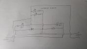
Some electronics help please to check what I have sketched out.

This is an idea for some electrical wiring internal to a trams trailer, where tram is noted this is a two wire connection to the powered tram.

What I want to do is operate the trailers red tail lamp dependant on which end the tram is connected (only the rear end lit at any time) and use the same two wire connection to power the trailers internal lighting regardless as to which end the tram is connected.

The LEDs are teenie weenie with minimal power requirements.

My question is, will this simple circuit work and what rating would I need for the diodes?

Thanks to anyone who can help.

David
 

Attachments

  • 20211012_212905.jpg
    20211012_212905.jpg
    241 KB · Views: 0
Are you using DC or DCC? I would have a common +ve and -ve supply in your trailer and arrange for the tail lights to be lit accordingly.

It depends on the rating of the LED, but if you try a resistance of 1K , then should be close enough for a reasonable level of intensity....
 
You really need to know the spec for your LEDs to design a voltage reduction circuit.

Using LEDs, you don't need to switch them if you wire them to the motor leads - you just need to wire them opposite to each other and the right way to the motor by trial error.

The interior lights can be wired to the motor leads via a rectifier.
 
Are you using DC or DCC? I would have a common +ve and -ve supply in your trailer and arrange for the tail lights to be lit accordingly.

It depends on the rating of the LED, but if you try a resistance of 1K , then should be close enough for a reasonable level of intensity....
All my trams are battery powered, the trailer lights are already installed, at present the first trailer that is ready to roll has batteries for the internal lighting, the idea behind my sketch was do do away with the trailer batteries and power everything from the trams power car.

The LEDs are 12v rated, everything works I just want to simplify things and do away with the trailer carrying batteries.

It's the diode rating that I would like some advice with, the LED's came with resistors attached, thanks.

David
 
As you have said, the LEDs take very little current, so 'almost any' diode will do the job for you..

1N4001 diodes, are rated at (up to) 50V and 1Amp... This will be plenty.

PhilP
 
  • So, you have a connector at each end of the car.
  • you want the interior lights on all the time
  • you want the led on the end of the car that is not coupled to be lit
  • I assume that plus and minus on your 2 connections never varies.

Almost right... you made a common minus, good... but your interior lights are backwards... reverse them and you are fine, the current circuit will never light them... (trace your plus inputs, they don't get to the back side of the interior lights)

I assume you drew it "positionally", i.e. the connector on the right will light the lamp on the left, i.e. the end that is not plugged in is lit...

Looks fine otherwise... I agree with the previous recommendation on the diodes.

Greg
 
Hey bottom line is there cheap LEDS if there even close to the voltage and you have good wiring (test build outside the cars) and hook it up. Your not build a controller or a pc getting all involved with ohms law and the math for some simple leds is funny to me (I’m a high voltage electrician by trade) I’ve had 12vdc rated leds hooked up to my massoth track (22vac)for ever now, That almost never turn off and in I’d say in a years time I’ve burnt out 2 of 30+ leds on my layout. So just have fun and build it and they will either smoke and burn out right away or be dim (over powered or under powered) and make changes. As needed and adding a capacitor to leds makes them operate and look like normal everyday lights not instant on or off.

And to anyone who wants to come at me and talk sh*t just know….. I don’t care what you think because these are toys!!!! If I wanted to work on formulas for electrical components I’d be on the clock at work so just save it and tell him the lame way to do it so he never learns.

Good luck!
 
Agree with Greg that you need to swap around the polarity of the interior lighting LEDs, then all should be good.

Remember, LEDs are current sensitive rather than voltage, so there's not really such a thing as a 5v or 12v led, unless the current limiting resistor has been internally fitted to give a known light output at a specific voltage. LEDs will have a rated current and this is not always the same. I tend to use the same led type for everything, so that I can use 1 resistor to power the whole lighting system on the tram, but if you are mixing and matching, you may need to experiment a little.

The diode in parallel with the tail led may require a resistor, as the voltage drop alone may not be enough to allow enough current to flow through the tail led. If so, you can omit the resistors to the interior lighting leds and juggle the other 2 values until satisfactory illumination is available to both.
 
Well spotted on the interior lights, they are presently wired up correctly, it's my sketch which is wrong.

Thanks all, it's been more years than I wish to remember since I was at college playing with electronics so all the advice is appreciated.

David
 
All my trams are battery powered, the trailer lights are already installed, at present the first trailer that is ready to roll has batteries for the internal lighting, the idea behind my sketch was do do away with the trailer batteries and power everything from the trams power car.

The LEDs are 12v rated, everything works I just want to simplify things and do away with the trailer carrying batteries.

It's the diode rating that I would like some advice with, the LED's came with resistors attached, thanks.

David
If the LEDs are 12v rated, why do you need a diode?

Light Emitting Diode - should do the trick on battery power - that's all I do with my battery locos (unless the voltage is more than 12v).
 
If the LEDs are 12v rated, why do you need a diode?

Light Emitting Diode - should do the trick on battery power - that's all I do with my battery locos (unless the voltage is more than 12v).
As per my previous post, it depends if the LEDs have internally fitted current limiting resistors. If they don't then you can fry them on 3V, let along 12V.
 
I am trying to only operate one of the red LEDs at any one time, hence the wee circuit.

David
Yep, OK, sorry if the previous comments have been a bit terse.

It struck me that, while the circuit would probably work, there's a lot of wires going into a small space and there may be simpler ways of doing it.

You say that you have 12v LEDs, so I am assuming (rather dangerous but never mind) that they have pre-installed resistors with red and black tail wires, and I'm assuming the battery supply for the trams is 12v.

So for the red tail lights, the simplest method of wiring is to wire them direct to the motor leads - let's say that the motor leads are green and yellow, then wire one black lead from the LED and one red lead from the other LED to the green wire, the other red lead and the other black lead to the yellow wire.

You then have to check that you have two tail lights rather than two red headlights :oops::oops: if the latter, the swap the 'pairs' on the green and yellow motor leads.

For the interior LEDs, you can buy a bridge rectifier component, they're fairly small and will take up less room and need less wiring than four diodes, and you wire the two alternating feeds into the motor wires, and the +ve and -ve feeds to the interior LEDs.

In my mind, that'll be a lot less wires :):):):)
Directional lighting for the power car is taken care of using the locoremote control unit, its the unpowered trailer which I am trying to sort out the wiring for, at the moment the trailer carries a battery pack for the internal lighting which I want to remove for weight reasons and to simplify things so that things work as soon as the trailer is connected to the powered tram. My sketch (although incorrect where the interior LEDs are shown) was drawn up to find a way of using just two wires between the tram and trailer to power both the interior lights and the rear dash board light, only the rear end of the vehicle light being illuminated with the lamp at the forward facing end of the vehicle remaining unlit.

I have drawn the sketch so that I should only have two wires going between each end of the tram under the floor.

I hope that explains what I am trying to achieve and the reason for the thread, thanks.
 
I think I understand what you are trying to acheive.

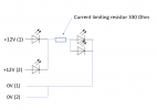
When you plug into socket "1", the tail light at the other end of the trailer comes on. Plug into socket "2" and the reverse happens. In all cases the illumination should be permanently on.

If so, this is quite simple to achieve. Please see the diagram below. This uses a single resistor to moderate current flow, but if you find one LED is brighter than the other, you may need to put a resistor in parallel with the LED which is too bright to reduce current flow through that LED.

1634121233059.png
 
Directional lighting for the power car is taken care of using the locoremote control unit, its the unpowered trailer which I am trying to sort out the wiring for, at the moment the trailer carries a battery pack for the internal lighting which I want to remove for weight reasons and to simplify things so that things work as soon as the trailer is connected to the powered tram. My sketch (although incorrect where the interior LEDs are shown) was drawn up to find a way of using just two wires between the tram and trailer to power both the interior lights and the rear dash board light, only the rear end of the vehicle light being illuminated with the lamp at the forward facing end of the vehicle remaining unlit.

I have drawn the sketch so that I should only have two wires going between each end of the tram under the floor.

I hope that explains what I am trying to achieve and the reason for the thread, thanks.
OK, so you take two wires from the motor to the trailer, and then wire as my suggestion - I think .......... :mm::mm: ....... it would still be less wiring, and less components.
 
A lot of my battery operated locos are wired for lights (LEDs) from the motor, though I have used duel colour (Red/White) and the appropriate colours shows according to direction.
 
Back
Top