Heavy gauge power connections-suggestions please.

Litninbolt

Registered
Country flag
So I have this new Digitrax EVOXD, and it has that screw barrier strip on it to connect the power supply and track connections. Being a good boy, I bought 12ga wire cause I’m running from the house, keeping the electronics indoors. The 12 ga wire does not fit in the barrier strip very well, and without much screw torque starts to push the 12 ga back out,

I have the big external supply and running multi-loco’s.

Any Body have good best practices/experience with wiring connections for this. I contacted them, they gave short answer, it will fit…my experience is different. Any ideas on getting a beefy connection from the system
 
If they say it will fit:
Strip a little more outer from the cable..
If multi-strand, use pliers to twist the strands nice and tight..
It may be you had not backed-off the screws quite enough, or the stripped cable did not seat far enough into the connector?

Good luck!

PhilP
 
I was helping out in the pet and wild bird feed section of the local Garden Centre...
A lady looked me up and down, and said "Have you got Fat Balls?"
To which I replied "No madam, it is the cut of these uniform trousers!"

The late,great Les Dawson..
Most of his material would be frowned upon, these days. :(:rolleyes:
 
So I have this new Digitrax EVOXD, and it has that screw barrier strip on it to connect the power supply and track connections. Being a good boy, I bought 12ga wire cause I’m running from the house, keeping the electronics indoors. The 12 ga wire does not fit in the barrier strip very well, and without much screw torque starts to push the 12 ga back out,

I have the big external supply and running multi-loco’s.

Any Body have good best practices/experience with wiring connections for this. I contacted them, they gave short answer, it will fit…my experience is different. Any ideas on getting a beefy connection from the system
As Phil has said strip back the insulation, twist the wires, put a bend in the wire and insert it under screw from the LH side so that when the screw is tightened the wire is drawn around the screw.
When stripping back the insulation do not remove it completely from the wire leaving a gap between the 2 pieces, the piece that is going to be removed can then be used to twist the wires by rolling it between finger and thumb, this gives a neater tighter twist than using pliers.

If the above fails to work use a crimp that fits under the screw and solder it to the wire the colour of the plastic insulating piece is a guide to the wire diameter that it will accept. I cut the plastic off then crush it onto the wire then solder some heatshrink can be used to designate polarity for DC red+ve black -ve
 
The 12 ga wire does not fit in the barrier strip very well, and without much screw torque starts to push the 12 ga back out,

It seems like you should take a look at ring connectors to put on your wire end. There are solder and crimp versions readily available at most auto parts stores.Ring terminals.jpg
 
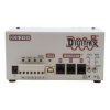
Are we talking about one of these ? If so I assume the numbered positions bottom left are what you are trying to insert wires into. Or is there somewhere else. Then, as said by others, strip insulation just enough so you can insert wire up into the terminal fully. If stranded wire, and it fits, without any trimming down, tin the ends of the wire to make a good fit and contact. If not select a lighter gauge wire that fits easily. Max

digitrax.jpg
 
Are we talking about one of these ? If so I assume the numbered positions bottom left are what you are trying to insert wires into. Or is there somewhere else. Then, as said by others, strip insulation just enough so you can insert wire up into the terminal fully. If stranded wire, and it fits, without any trimming down, tin the ends of the wire to make a good fit and contact. If not select a lighter gauge wire that fits easily. Max

View attachment 288728
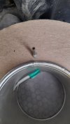
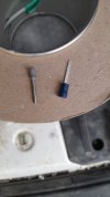
If its one of those, boot-lace ferrules might be the answer
20210809_185442.jpg20210809_185430.jpg
 
Boot-lace ferrules. Those are sweet if you have them. I must confess to just tinning the ends of my stranded wire to get the same basic end as a boot-lace ferrule. But then, sometimes it's just too big for those type of connector openings. I have squeezed them in pliers to make them more square to fit the opening. I have filed them slightly for the same problem. I have also, in a pinch taken a spade connector (those u shaped crimp on things), crimped it to the wire, and then cut off one leg (if the amperage was low) or folded both legs together to get a slightly smaller square end (similar to filing the round tinned wire to a square profile). Of course, any reduction in the wire size at the end of your wire will reduce its amps capacity. But, if the connector won't take it anyhow, maybe it was not intended for 12 gauge wire in the first place?

This brings us to the "It's time to look up some specs" portion of our program. The Digitrax EVOXD with its DCS 210+ shows a rating of:
  • 5 amps of power with included PS615 power supply
  • 8 amps with PS2012E power supply (sold separately)

So, even if you spring for the bigger power supply, It seems that you will be outputting 8 amps at the max setting. I am not an electrician, but my friends who are (and you can look this up to confirm it) tell me that when doing house wiring, code requires 12 gauge wire for 20 amp circuits and 14 gauge wire for 15 amp circuits. Your potential is 8 amps. I don't know how far it is from the house to your railroad, but it is quite a few feet from my electrical panel to the other end of my house. Of course, we are talking about 120 volts of AC power in that example.

More important to our situation may be voltage loss at a certain amount of amps, volts, distance. The second link here show a voltage drop of just a couple of volts at 8 amps, 24 volts, 100 feet for a pair of 14 gauge wires. And that is with a LOAD of 8 amps. At a load of 2 amps you only loose a half a volt.

A wire length calculator:

A voltage drop calculator:


BUT....all that being said, we could use some practical experience opinions here. What do you all use at what footage to how many connections on your empires? I have been digging on Greg's site but have not found wire size at distance recommendations there...yet....

ALSO....a thought :whew:......if you run a piece of track into your house, or very near your house, then your feeders don't have to go very far and your "wire gauge" for the rest of the railroad is whatever the rail size and type is....right? ;)
 
ALSO....a thought :whew:......if you run a piece of track into your house, or very near your house, then your feeders don't have to go very far and your "wire gauge" for the rest of the railroad is whatever the rail size and type is....right?
Yes and no. If your rr has continuous welded rail yes. Otherwise no, every joint is a potential spot of high resistance and there are likely to be a lot of them! More importantly, it only takes one to ruin your day! If you solder jumpers across each joint - great. But, that's too much work for me and I'm no good at soldering to code 332 rail anyway! I use rail clamps with "conductive" paste on all my rail joints which is almost as good as soldering a jumper.

I think you may have entered the wrong info into the voltage drop calculator for your example. I get a drop of just over 4V (4.28) at 24V and 8 amps for your 100 ft 14 awg run. That's almost a 20% drop in voltage and you haven't taken voltage drop in the track into account yet!

I have about a 70 ft run of 12 awg for my feeders. I also have a 12 awg power bus wire with multiple drops feeding each electrically isolated track zone. I would recommend at least 2 drops per zone. I also have about a 5 ft run of roughly 16 awg from my boosters to the feeders. The voltage drop in this 5 ft run is negligible. (That's how to solve the "It's too big to fit" issue. Solder on a short piece of the largest wire that does fit. And, don't forget to put heat shrink on the joints.)
 
I agree and accept your corrections. This stuff can get complex quickly and has a lot of variables. I am interested to finally find someone who actually runs a bus line in G scale. Most have said the track (with properly cared for joints, as you mention) is enough of a "bus" in itself. however, if you are isolating sections, some kind of multiple feeders would be required. I suppose that is not strictly a "bus line" as I am used to using on HO scale railroads where I agree that multiple feeders are a must to rectify loss through any unsoldered feeders. Looks like we agree that a shorter run from the booster to the Bus lines or rails would be acceptable.

I am curious about what I am doing wrong with the voltage drop calculator? I am attaching a snapshot of what I put in. Where have I gone wrong?Voltage Drop Calculator pic.JPG
 
I also agree that "soldering" all the joints is a big job. I have a rig for doing so in a "resistance soldering" fashion. It consists of a battery charger, foot pedal, big alligator clamps, and the correct welding rod. Holes are drilled in the web at an angle, 12 gauge wire is inserted, and then a good ZAP with the aforementioned rig makes a pretty permanent connection. But I only drag it out when it's REALLY needed.
 
You've got too many conductors! The correct setting is a single set. What you've got is a pair of 14 awg wire sets (in parallel is the clue) selected which doubles the effective wire cross-section and halves the resistance.
 
Or maybe the idea of carefully filing the end of the 12 gauge wire to a nice flat (square?) Cross section so the screw bites into the flat nicely?
 
Back
Top