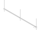
How to feed a 120m track

Microgreens

Registered
Country flag
HI!

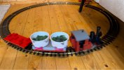
I want to build a railway inside my greenhouse to transport our flowers to the warehouse for packing. I have bought a building block starter set to test and it worked perfectly!
The system will be U shapped, with a total of 120 meters, with a single track, no turnouts. The central station 3 will control the train and automations
Along the track I plan to install contact point that are activated via magnet on the train so I can know where the train is and also so I can send it to specific points on the track.

My question is, how should I feed this track? Is 1 cable (1 injection point) enough for a track this size? Or should I use multiple points along the track? If so, how is this wiring done?
I bought a S88 link to connect to the contacts on the track, can I have is near the central station and run cables along the length of the track to connect to the contacts? Or is 120 meters too much for these feedback contacts to work?

I have watched countless hours of videos on youtube, read instruction manuals and search the web for these answers, but wasn't able to find anything usefull. Is someone can help me I would be very greatfull!

Thanks,
Tomás
 

Attachments

  • IMG_579BA74F3923-1.jpeg
    IMG_579BA74F3923-1.jpeg
    284.8 KB · Views: 0
Welcome to the forum Tomas.

One feed is fine, but multiple feeds are better. I have only one feed to my track which goes down the garden around 40 metres.

Top tip, a little bit of copper slip, say half a pea size, in the joiners help, or better still, rail clamps, but you seem to be managing fine as it is!

I don't use the CS, having an older Massoth system, so I will defer to others more familiar regarding the S88....
 
What Gizzy says is sound. However for your circumstances where you are relying on your line for your business I would suggest more effective methods would be of help, firstly to allow your automation but more importantly to have track sections for fault finding. I would certainly also suggest Massoth Track Clamps, they have a screw fit that lightly bites into the rail for good long term track power connection, but those same screws can be used for track power in your sections. I tend to create a loop a suitable size that the screw will fit into, once created a spot of solder on the loop will give it good strength when you screw in place. The sections can be created using Isolation Clamps again for reliability I would suggest a feed at each end of the section going back to a joint of the other end then back to a panel featuring good sold Double Pole Centre Off switches. I would think about 5 ir 6 sections would suit you.

As for automation I will leave that to others for DCC, but if you use Clamps as I suggested setting additional sections for automation stop starts ( if indeed sections are required) would be simple.

Good luck with your interesting system, be good to see it in action on a You Tube Vid when fully working much as the Restraunt in Prague has posted.
 
Welcome to the forum Tomas.

One feed is fine, but multiple feeds are better. I have only one feed to my track which goes down the garden around 40 metres.

Top tip, a little bit of copper slip, say half a pea size, in the joiners help, or better still, rail clamps, but you seem to be managing fine as it is!

I don't use the CS, having an older Massoth system, so I will defer to others more familiar regarding the S88....
What Gizzy says is sound. However for your circumstances where you are relying on your line for your business I would suggest more effective methods would be of help, firstly to allow your automation but more importantly to have track sections for fault finding. I would certainly also suggest Massoth Track Clamps, they have a screw fit that lightly bites into the rail for good long term track power connection, but those same screws can be used for track power in your sections. I tend to create a loop a suitable size that the screw will fit into, once created a spot of solder on the loop will give it good strength when you screw in place. The sections can be created using Isolation Clamps again for reliability I would suggest a feed at each end of the section going back to a joint of the other end then back to a panel featuring good sold Double Pole Centre Off switches. I would think about 5 ir 6 sections would suit you.

As for automation I will leave that to others for DCC, but if you use Clamps as I suggested setting additional sections for automation stop starts ( if indeed sections are required) would be simple.

Good luck with your interesting system, be good to see it in action on a You Tube Vid when fully working much as the Restraunt in Prague has posted.
Thank you both for your help!
I intend to build this with Thiel track because they sell them in 2.75m sections, so this will guarantee the minimum amount of connections possible. I will also be using clamps with screws to connect every track.

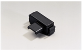
From what I read, it is not necessary to isolate tracks to know where the train is if I use a magnet on the train and contact system like this:

Screenshot 2024-08-05 at 15.00.09.png

The contact will send a short signal to the central station via the S88 indicating that the train is passing over it. With the CS3 I can then automate actions when the train goes over it.

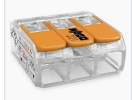
To make the various injection points, do I have to use any particular accessory? Or do I just run the cable alongside the line, cut it and connect it with a connector like this one?

Screenshot 2024-08-05 at 15.04.24.png


If I have isolated track sections, do I use the same power source and cable and connect it to the multiple track sections, or do I need a booster or something like that for each section?

Thanks
ps: I promise I will make a video, once this is installed
 
Thank you both for your help!
I intend to build this with Thiel track because they sell them in 2.75m sections, so this will guarantee the minimum amount of connections possible. I will also be using clamps with screws to connect every track.

From what I read, it is not necessary to isolate tracks to know where the train is if I use a magnet on the train and contact system like this:

View attachment 331272

The contact will send a short signal to the central station via the S88 indicating that the train is passing over it. With the CS3 I can then automate actions when the train goes over it.

To make the various injection points, do I have to use any particular accessory? Or do I just run the cable alongside the line, cut it and connect it with a connector like this one?

View attachment 331273


If I have isolated track sections, do I use the same power source and cable and connect it to the multiple track sections, or do I need a booster or something like that for each section?

Thanks
ps: I promise I will make a video, once this is installed
Those connectors will be fine but to keep things neat and cut as you say may I suggest you put in trunking, the type that has removable top. Size as to fit your connectors. I use this method to represent prototype trunking on my outside line, of course I use smaller trunking but I do not use connectors like you are proposing. You will not need to worry about the prototype look but it will help keep things neat and tidy in your commercial environment. You could colour mark the tops of the connectors to indicate the sections if you have more close together, a likelehood when you install the the magnets. Surprising how complex wiring can become even on what is thouggt to be a simple layout. Plan and record you wire runs on paper. My line is now dead rail so all the wires removed but trunking still in place for my pneumatic pipe runs for points and signals.
 
Interesting and different requirements for a railway! I would have thought that if you are using an 'U' shaped track why not put power feeds at each end? Personally I would do that then see if your trains run as you want as you can always put in extra power feeds afterwards. If you are going to use power districts then each will need its own supply, it depends on your base station as to how much power can be supplied, a booster would probably only be needed if there is too much of a power drop at the furthest point of the line or the districts inbetween.
I could be wrong, I usually am.
 
Those connectors will be fine but to keep things neat and cut as you say may I suggest you put in trunking, the type that has removable top. Size as to fit your connectors. I use this method to represent prototype trunking on my outside line, of course I use smaller trunking but I do not use connectors like you are proposing. You will not need to worry about the prototype look but it will help keep things neat and tidy in your commercial environment. You could colour mark the tops of the connectors to indicate the sections if you have more close together, a likelehood when you install the the magnets. Surprising how complex wiring can become even on what is thouggt to be a simple layout. Plan and record you wire runs on paper. My line is now dead rail so all the wires removed but trunking still in place for my pneumatic pipe runs for points and signals.
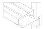
I wil mount the track on this metal support so all the wires will be hidden under it
Screenshot 2024-08-05 at 16.18.00.pngScreenshot 2024-08-05 at 16.18.21.png
 
Interesting and different requirements for a railway! I would have thought that if you are using an 'U' shaped track why not put power feeds at each end? Personally I would do that then see if your trains run as you want as you can always put in extra power feeds afterwards. If you are going to use power districts then each will need its own supply, it depends on your base station as to how much power can be supplied, a booster would probably only be needed if there is too much of a power drop at the furthest point of the line or the districts inbetween.
I could be wrong, I usually am.
I like your suggestion! Start simple, then if it doesn't work properly I can always add more.
That's what I thought about the isolated sections, I would need a power source for each. That's why I prefer the magnets, but I have not tried them yet. I ordered a few allong with the CS3 to test this in a small scale before installing the big track.

By the way, I know I'm not supposed to go off topic, but I tried to reply to your DM and I get this error. I'm in Portugal

Screenshot 2024-08-05 at 16.14.37.png
 
I like your suggestion! Start simple, then if it doesn't work properly I can always add more.
That's what I thought about the isolated sections, I would need a power source for each. That's why I prefer the magnets, but I have not tried them yet. I ordered a few allong with the CS3 to test this in a small scale before installing the big track.
I used the magnet system (known as EPL to LGB) when I ran a G scale railway. It is nothing fancy but if you think along logically - it can seem weird at first - then it all runs well.
By the way, I know I'm not supposed to go off topic, but I tried to reply to your DM and I get this error. I'm in Portugal

View attachment 331280
This is not really off topic, it is your thread after all. The error, like I wrote, is that two countries show up. I think the Administrator will look into it - above my paygrade.
 
Interesting and different requirements for a railway! I would have thought that if you are using an 'U' shaped track why not put power feeds at each end? Personally I would do that then see if your trains run as you want as you can always put in extra power feeds afterwards. If you are going to use power districts then each will need its own supply, it depends on your base station as to how much power can be supplied, a booster would probably only be needed if there is too much of a power drop at the furthest point of the line or the districts in between.
I could be wrong, I usually am.
Feeds at both ends will provide a level of redundancy if one connection fails, the more feeds the higher the redundancy..
Personally seeing as this is going to be a permanent install I would solder the feed wires directly to the rail and solder the joints or at least use jumper wires around them.
The reason I say this is that if your shadehouse is any thing like mine (I grow orchids) the line will be subject to irrigation and the level of humidity would be elevated therefore mechanical clamps will be susceptible the water ingress.
Soldering will ensure a strong electrical connection, remove mechanical connectors which will add potential points of failure (the fewer of these the better) and reduce/remove water issues.
 
Newly registered members have some limits on what they can do on the Forum.

I believe one of them is personal messaging?

A Moderator/Admin usually sorts this, once you have made a few legitimate posts.

PhilP
 
Thank you GAP GAP for your suggestion! I think once I have the track installed and everything working as intended I will solder the joins and connections, as suggested.
 
Welcome to the forum Tomas.

One feed is fine, but multiple feeds are better. I have only one feed to my track which goes down the garden around 40 metres.

Top tip, a little bit of copper slip, say half a pea size, in the joiners help, or better still, rail clamps, but you seem to be managing fine as it is!

I don't use the CS, having an older Massoth system, so I will defer to others more familiar regarding the S88....

I should point out the 'copper slip' in the brand-name Copperslip - a light grease containing a very high level of micropowder copper in it. It is used as a conducting lubricant and also for lubricating the backs of brake pads to prevent them squeaking.
 
I would be wary of running the magnet contact wiring together with the DCC bus wiring.

I had a quick look at the S88 Link manual and it doesn't state what voltage is supplied to the reed switches - I suspect low voltage (e.g. 5v) but I could be wrong.

If you are planning on running long runs of cable they will be susceptible to induced voltages - in this instance where the magnetic field generated by the DCC bus wiring is picked up by the sensor wiring.
This may cause spurious activation of the sensors.

It may be a better idea to run a couple of S88 link boxes connected by the S88 bus, thus keeping your sensor wires short and less susceptible to those induced voltages.

You could also run shielded cable for either the DCC bus or sensors - I suspect that might be overkill though (and it will cost more).
 
Run the S88 wires as twisted pairs.

Unless you know what you are doing, shielded cables can make pickup worse! - Only connect the shield to ground at one end.

PhilP
 
Microgreens joined just last Saturday so he will be limited on PM’s for a while. Wish I could remember how long that is!
 
Over here in New England we use the wire used for outdoor lighting, direct bury well insulated
 
Tomas, I am sure you have done your homework but I am wondering about the whole suitability of what are essentially 45 mm gauged "hobby" vehicles, track and control systems for a heavy duty cycle commercial application, and type of loads you might well be expecting.

Yes, there are one or two very well known establishments that use the like for commercial delivery, indoors, of food and drink to diners from serving areas. They are quite compact and have a redundant back up system, waiting staff. Have you spoken to these operators about the reliability and management of their systems ? There are other businesses that use model railways but only as "set dressing" to provide a point of interest.

Could you provide an example of the type of stock you are moving ? Not trying to be negative, but I think you need something far more robust and proven in this application. Max
 
Back
Top