Indicators

DafyddElvy

1:22.5 & 15mm Scale Trams, , NG Steam Railways
Country flag
I want to fit indicators to my trams, similar to the type fitted to road vehicles.
My trams are battery powered, controlled using a Locoremote maxi unit.

I have contacted the man from Locoremote who says he can't think of a way to have working indicators operated from his units.

I wondered if anyone here might have any clever ideas about how to fit working indicators to my trams??? I
 
Are you looking for advice on how to make the indicators or how to control them, or both? If the former I would think Peter ( schienenkönig schienenkönig ) would be your man as his model trams often feature working indicators, but his are DCC controlled I believe.
 
An oscillator / 555 timer circuit to give you the 'flash'..
Can the Locoremote drive a servo? - you could use a servo to switch the 'flash' to the correct side of the tram.

A conventional RC system could do it, obviously.

PhilP
 
I've not yet researched enough to offer a detailed answer, but a simple and cheap 2 channel RF wireless remote fob (two button, locking operation, press second time to disengage), communicating to relays powering flashing yellow LEDs left and right would perhaps work. These kits are availabIe for a few quid on the usual sites, like Amazon, and the remote end can work with the low voltage power already available in the tram.

I have a project for next year's worklist, to operate a rail gate via a very slow motor, which is a vaguely similar scenario, as I don't want to trail any more wires around the garden - one button to open, the second to close, perhaps with a DPDT relay to reverse the polarity, and that was the low cost control solution I had planned to investigate first. I suppose another possible solution might be the reed switch + track magnet route, if you want indication at specific points on the track, but that's way beyond my experience :)
 
Last edited:
Don't know much about the Locoremote - had a quick look at the website, couldn't find that much tech info.

The manual gives instruction on fitting Mylocosound cards - which means the Sound card interface pins are likely low side logic switches.

You could use a 555 timer circuit for each indicator as suggested - using a 2 Sound outputs on the Locoremote to switch an N-Channel Transistor / MOSFET which would switch the ground to each of the 555 timer circuits.

Or - and this is maybe sledgehammer to crack a walnut - but get hold of an Arduino Mini / Micro / clone. One of these will be smaller than 2 555 circuits, plus all you need to hook it up to the Locoremote and LED's is resistors.

The code for blinking an LED is really easy and there are many examples available - It would probably take 10 mins to write the code - happy to have a go.
 
I would have thought that flashing LED’s would do the job. Perhaps controled from a chip using a couple of the lighting circuits?
 
I have a flashing LED fitted to my railbus, no fancy electronics everything in the LED, you just need to switch them on.
 
Are you looking for advice on how to make the indicators or how to control them, or both? If the former I would think Peter ( schienenkönig schienenkönig ) would be your man as his model trams often feature working indicators, but his are DCC controlled I believe.
Yes and yes.

I have done the normal www search and come up blank, I am pondering all the good ideas received so far, one of the problems is though that the suggestions have made me think about other things I could add to my models. I'm not sure I can handle the stress of the new ideas entering my grey matter

Some pondering required.
 
Thanks all for the normal helpful responses, and I am going to ask Mr Locoremote about how his units communicate with mylocosound and see what that brings.

Please keep the ideas flowing, they all provide excercise for the grey mater, thank.
 
Yes and yes.

I have done the normal www search and come up blank, I am pondering all the good ideas received so far, one of the problems is though that the suggestions have made me think about other things I could add to my models. I'm not sure I can handle the stress of the new ideas entering my grey matter

Some pondering required.
So........
Brake lights..
Reversing lights..
Opening doors when you stop, and passenger step lights..
Reversing lights, with hazards on, and warning bleeps..
:devil::devil::devil::devil::devil:

PhilP
Thanks all for the normal helpful responses, and I am going to ask Mr Locoremote about how his units communicate with mylocosound and see what that brings.

Please keep the ideas flowing, they all provide excercise for the grey mater, thank.
The MLS card just needs to trigger input grounding, so that is what you will get from the Locoremote.

As the MLS card is running from full battery voltage, and the Locoremote is running (logic-wise) from a lower internal voltage, you should fit a current limiting resistor in the trigger lead. This reduces the potential (Sorry!) for stray current to flow between the devices, and do any damage.
If the Locoremote outputs are open collector (or Mosfet) switches, then you do not need a resistor.

PhilP
 
With 6 outputs from the Locoremote - two light outputs which are 150ma@3.3v and 4 logic level sound outputs, one of which is either latching or momentary, the other 3 send a 0.5sec low pulse when pressed - which basically rules out a simple 555 circuit (without some clever timed latching) and the use of flashing LEDs with the sound outputs.

Using those 0.5 second triggers to trigger an Arduino to perform an action would be my goto soulotuion for making all the things happen. Makes the code a little more interesting to write but not too bad.
 
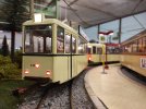
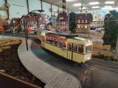
This is a tram and trailer from the former Hagener Straßenbahn. It has been a freelance train before and I transformed it to this original tram 336 and trailor 133. There is still one train existing at the tram Museum Wuppertal.
But back to the question. Tram and trailer have indicators, working brake lights, head and rear lights and interior lighting. The lights are controlled with an esu driving decoder. The trailer has an esu function decoder.
002.jpg
 

Attachments

  • 001.jpg
    001.jpg
    320.9 KB · Views: 1
To buffer a low current signal you can use 5545X (x can be 1,2,3, or4) which has 2 200ma and up to 30 volt output control. Can be triggered by less than 5ma. The 4 versions are for and, nand, nor etc. operations. 5 volt powered 8 pin IC with 2 separate input/outputs but NOT isolated.
 
This is a tram and trailer from the former Hagener Straßenbahn. It has been a freelance train before and I transformed it to this original tram 336 and trailor 133. There is still one train existing at the tram Museum Wuppertal.
But back to the question. Tram and trailer have indicators, working brake lights, head and rear lights and interior lighting. The lights are controlled with an esu driving decoder. The trailer has an esu function decoder.
View attachment 306423
If I was using DCC it would be simple, but I am using battery power and Locoremote maxi units for control.
I have interior lighting as well as directional lights, I just thought it would be nice to also have indicators.

There will be a way that suits me to do the thing I want, I just need to find the best option for me.
 
I want to fit indicators to my trams, similar to the type fitted to road vehicles.
My trams are battery powered, controlled using a Locoremote maxi unit.

I have contacted the man from Locoremote who says he can't think of a way to have working indicators operated from his units.

I wondered if anyone here might have any clever ideas about how to fit working indicators to my trams??? I
I would go for the BMW type indicators - they never come on :giggle::giggle::giggle:
 
Back
Top