Thought I'd summarize installing a Massoth XLS sound decoder in an early digital era analog LGB Ge 4/4 III loco, in my case a loco from the No. 70642 LGB 30 Year Anniversary set. These are locos with the 6 white dot digital ready sticker on the bottom. See LGB Decoder Stickers. These instructions can be applied to any large scale two motor sound decoder such as those by ESU or Zimo also. The Massoth XLS connection diagram can be used as a guide. The Massoth ribbon cable referenced in step 3 should still be purchased. Also, some crimp-on plugs should be bought to fabricate the other needed connection leads. The crimp-on plugs are seen near the bottom of this page AllAboutLGB: LGB train Repair Parts. The crimp-on plugs are also available here 60037 Power Pickup Plug, 10 pieces and here Kabelschuhe System LGB®, 10 Stück. I keep a stock of these with my spare parts just to have them handy.
1. This generation of "digital ready" locos (6 white dot sticker) have function control by serial pulses of the decoder A1 function output.
2. The Massoth product number for the XLS decoder with the RhB Ge 4/4 III Sound Project pre-installed is 8230042. Ordering this part number gets you the eMotion XLS sound decoder with the Ge 4/4 III sounds installed, function keys configured and the correct speaker. It does not include a needed six conductor ribbon connector or a second set of 4 green, yellow, brown and white single conductor wires needed for getting track power from and motor power to the motor block in the second bogie.
3. The Massoth part number for the needed ribbon cable with correct plug is 8312061. Order it when you order the decoder. You may want to order the Massoth eMotion Reed Contact Switch No. 8242020 and eMotion Volume Control Board No. 8242010 too. Ge 4/4 III Sound Project is configured so the reed switch will let track magnets trigger the loco whistle. The volume control gives manual control of the speaker volume.
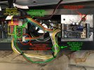
4. The installation is exactly as shown in the eMotion XLS Installation Manual on page 15 with the exception of the additional 4 single conductor wires needed for the second bogie. The loco is opened up as described on page 10 of the instruction brochure under the heading "Operation with two pantographs raised". Here is a link to the brochure thanks to forum member Software Tools: http://www.gbdb.info/data/manual/LGB/20420.pdf. I mounted the XLS decoder to one of the loco weights. I used one existing hole in the weight and drilled a second to mount the decoder. It was secured with the self-threading screws included with the decoder. I found it easier to connect the decoder interface wires to the decoder before mounting it. Then, after mounting the decoder, the wires were just plugged into the correct spots on the loco decoder interface board.
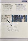
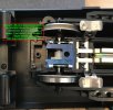
5. At this point the reed switch can be added if desired. The Massoth eMotion Reed Switch Board is designed for LGB motor blocks. While the loco is open one of the bogies needs to be removed to put in the reed switch. Screw 92 that passes through plastic washer 48 on the loco exploded diagram, https://www.onlytrains.com/manuals/20420-1.pdf, will release the bogie. The motor block ribbon cable can be unplugged at the bogie to make installation easier. A hole needs to be drilled in the top of the motor block for the reed switch leads. Re-install the bogie. I wired the switch as shown on page 19 of the eMotion XLS Installation Manual.
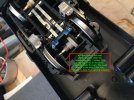
6. The speaker is mounted in the "center detail molding" removed to open up the loco. There is a ring on the inside of the center detail that locates the speaker along with 4 spots for self-threading screws. The center detail molding needs to be drilled to let the sound out. Do this before mounting the speaker! I copied this particular hole pattern after a more recent MLGB Ge 4/4 III loco. This is a good time to mount the volume control board if you are going to install one. It should be mounted on the "center detail molding" too. Find a spot to drill holes for potentiometer stem and mounting screws that will not interfere with anything. Temporarily put the center detail molding back in place to find a good spot if needed. (I did not install a manual volume control. I adjusted the maximum volume to my liking with the decoder Total Volume CV which is CV200 for the XLS.)
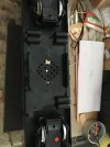
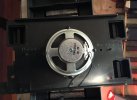
7. Double check that the 6 switches on the gray dip switch block that set the loco from analog only to DCC power are set to "OFF". If you power up the loco with them "ON" you may destroy the decoder! Temporarily attach the "center detail molding back on the loco chassis. Plug the speaker and volume control board leads into their sockets on the XLS decoder. Put the body back on but don't screw it down yet.
8. Time to test the installation. Put the loco on a DCC programming track and If you are using a XLS decoder change CV29 to 6 for 28/128 speed steps. The Sound project default is 14 speed steps, CV29=4. (If you are using an old LGB MTS serial DCC system leave CV29 set to the default value of 4.) Now put the loco on a test track or preferably a rolling road and check the light and motor operation in both directions with DCC control. Both pantographs should go up as soon as DCC power is applied and stay up. If, not check that the clips are not holding them down. Remember the decoder DCC address will be 3 unless you already changed it. You can also check the DCC decoder analog operation. Lights, sound, and the rear pan for the direction of travel should go up and the front pan go down as the voltage is increased. Lights and pantographs should swap when the direction is reversed with analog control.
9. Now change other decoder CVs as necessary. Check CV49, the Massoth Configuration CV. Even though the pantographs respond to serial pulses from A1 CV49 should have bits 0, and 3 "off". Bit 0 "off" sets the decoder for normal parallel data operation. (Leave/check that Bit 0 is "on" if using the old LGB MTS serial central station.) Bit 3 "off" sets A1 for standard output. You do NOT want A1 set for "A1 Output with rapid serial pulse" even if using an old LGB serial MTS. The Massoth Ge 4/4 III Sound Project comes with a forward direction only A1 output assigned to F10. F10 also has the ventilation sound assigned to it. (The Sound project sheet shows the F7 key operating decoder output A1, CV54 = 7. I believe this is incorrect. When I loaded the Sound project CV54 was given the value 138, the setting for forward only on F10, 128+10) I suggest changing it to operate in both forward and reverse loco directions and to reassign it to either the F11 or F12 key which have the pantograph up and pantograph down sounds assigned. This is done by changing CV 54 to 11 (for F11) or 12 (for F12).
NOTE: I HAVE NOT VERIFIED THE ABOVE RECOMMENDED SETTING FOR OLD LGB SERIAL COMMAND MTS SYSTEMS. You are on your own here!
10. One final but critical item needs to be taken care of at your central station or other DCC control device. Whichever F key you assigned to operate the A1 decoder output for this loco must be configured as "switching" on your control device. Not momentary or timed. When set to switching two taps of the F key should lower the front (Cab I) pan. Another two taps will cause it to raise again. A series of three taps of the F key do the same for the rear (Cab II) pan.
11. If everything is working properly button up the loco and change the DCC address if you want.
12. Enjoy your newly digitized Ge 4/4 III !
1. This generation of "digital ready" locos (6 white dot sticker) have function control by serial pulses of the decoder A1 function output.
2. The Massoth product number for the XLS decoder with the RhB Ge 4/4 III Sound Project pre-installed is 8230042. Ordering this part number gets you the eMotion XLS sound decoder with the Ge 4/4 III sounds installed, function keys configured and the correct speaker. It does not include a needed six conductor ribbon connector or a second set of 4 green, yellow, brown and white single conductor wires needed for getting track power from and motor power to the motor block in the second bogie.
3. The Massoth part number for the needed ribbon cable with correct plug is 8312061. Order it when you order the decoder. You may want to order the Massoth eMotion Reed Contact Switch No. 8242020 and eMotion Volume Control Board No. 8242010 too. Ge 4/4 III Sound Project is configured so the reed switch will let track magnets trigger the loco whistle. The volume control gives manual control of the speaker volume.
4. The installation is exactly as shown in the eMotion XLS Installation Manual on page 15 with the exception of the additional 4 single conductor wires needed for the second bogie. The loco is opened up as described on page 10 of the instruction brochure under the heading "Operation with two pantographs raised". Here is a link to the brochure thanks to forum member Software Tools: http://www.gbdb.info/data/manual/LGB/20420.pdf. I mounted the XLS decoder to one of the loco weights. I used one existing hole in the weight and drilled a second to mount the decoder. It was secured with the self-threading screws included with the decoder. I found it easier to connect the decoder interface wires to the decoder before mounting it. Then, after mounting the decoder, the wires were just plugged into the correct spots on the loco decoder interface board.


5. At this point the reed switch can be added if desired. The Massoth eMotion Reed Switch Board is designed for LGB motor blocks. While the loco is open one of the bogies needs to be removed to put in the reed switch. Screw 92 that passes through plastic washer 48 on the loco exploded diagram, https://www.onlytrains.com/manuals/20420-1.pdf, will release the bogie. The motor block ribbon cable can be unplugged at the bogie to make installation easier. A hole needs to be drilled in the top of the motor block for the reed switch leads. Re-install the bogie. I wired the switch as shown on page 19 of the eMotion XLS Installation Manual.


6. The speaker is mounted in the "center detail molding" removed to open up the loco. There is a ring on the inside of the center detail that locates the speaker along with 4 spots for self-threading screws. The center detail molding needs to be drilled to let the sound out. Do this before mounting the speaker! I copied this particular hole pattern after a more recent MLGB Ge 4/4 III loco. This is a good time to mount the volume control board if you are going to install one. It should be mounted on the "center detail molding" too. Find a spot to drill holes for potentiometer stem and mounting screws that will not interfere with anything. Temporarily put the center detail molding back in place to find a good spot if needed. (I did not install a manual volume control. I adjusted the maximum volume to my liking with the decoder Total Volume CV which is CV200 for the XLS.)


7. Double check that the 6 switches on the gray dip switch block that set the loco from analog only to DCC power are set to "OFF". If you power up the loco with them "ON" you may destroy the decoder! Temporarily attach the "center detail molding back on the loco chassis. Plug the speaker and volume control board leads into their sockets on the XLS decoder. Put the body back on but don't screw it down yet.
8. Time to test the installation. Put the loco on a DCC programming track and If you are using a XLS decoder change CV29 to 6 for 28/128 speed steps. The Sound project default is 14 speed steps, CV29=4. (If you are using an old LGB MTS serial DCC system leave CV29 set to the default value of 4.) Now put the loco on a test track or preferably a rolling road and check the light and motor operation in both directions with DCC control. Both pantographs should go up as soon as DCC power is applied and stay up. If, not check that the clips are not holding them down. Remember the decoder DCC address will be 3 unless you already changed it. You can also check the DCC decoder analog operation. Lights, sound, and the rear pan for the direction of travel should go up and the front pan go down as the voltage is increased. Lights and pantographs should swap when the direction is reversed with analog control.
9. Now change other decoder CVs as necessary. Check CV49, the Massoth Configuration CV. Even though the pantographs respond to serial pulses from A1 CV49 should have bits 0, and 3 "off". Bit 0 "off" sets the decoder for normal parallel data operation. (Leave/check that Bit 0 is "on" if using the old LGB MTS serial central station.) Bit 3 "off" sets A1 for standard output. You do NOT want A1 set for "A1 Output with rapid serial pulse" even if using an old LGB serial MTS. The Massoth Ge 4/4 III Sound Project comes with a forward direction only A1 output assigned to F10. F10 also has the ventilation sound assigned to it. (The Sound project sheet shows the F7 key operating decoder output A1, CV54 = 7. I believe this is incorrect. When I loaded the Sound project CV54 was given the value 138, the setting for forward only on F10, 128+10) I suggest changing it to operate in both forward and reverse loco directions and to reassign it to either the F11 or F12 key which have the pantograph up and pantograph down sounds assigned. This is done by changing CV 54 to 11 (for F11) or 12 (for F12).
NOTE: I HAVE NOT VERIFIED THE ABOVE RECOMMENDED SETTING FOR OLD LGB SERIAL COMMAND MTS SYSTEMS. You are on your own here!
10. One final but critical item needs to be taken care of at your central station or other DCC control device. Whichever F key you assigned to operate the A1 decoder output for this loco must be configured as "switching" on your control device. Not momentary or timed. When set to switching two taps of the F key should lower the front (Cab I) pan. Another two taps will cause it to raise again. A series of three taps of the F key do the same for the rear (Cab II) pan.
11. If everything is working properly button up the loco and change the DCC address if you want.
12. Enjoy your newly digitized Ge 4/4 III !
Last edited:

