Isolating a passing loop

playmofire

Registered
Country flag
I'm planning a layout for the last Kirkbean Playmobil Exhibition including two passing loops on an oval, at any one time, one oval will have a train parked on it and the other will be empty while its train circulates the oval. The idea is that a train will run clockwise for a while and then be parked on the empty passing loop and the other train will then be released from its passing loop and circulate anti-clockwise, being returned to it after a few circuits and so on.

Clearly, the passing loops need to be isolated and I originally thought of doing so through the points at each end of the passing loops. However, it occurred to me that if there were an isolating point at the entry end of each passing loop and an LGB semaphore signal US style at the exit end of each loop, I could isolate the loops that way and release the trains under signals.

Is my thinking correct on this, please?
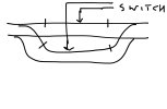
Both will have to be operated to isolate the loop, and if either is operated, then the loop becomes live. - So if the wrong point / signal is operated (with power on the mainline) the loco will run into a point set incorrectly.

Probably not likely to happen, as I assume trains running in one direction?

PhilP
To avoid this I am thinking of operating the signal via the exit point, using the LGB add-on double throw switch on the exit point, and the controller will be at "Off" during this operation.
 
I was thinking of inexperienced operators having a go..

PhilP
Ah, they're only allowed roundy-roundy the oval. I may also have the exploding goods van on a separate stretch of track for people to try coupling it up to loco and pulling it away from the flames
 
Some years ago when I created a temporary oval with a passing loop I used LGB isolating joiner on one rail at one end of the loop and a Playmobil 4373 sliding isolating switch on the same rail at the other end of the loop. Nice and simple and worked a treat :) I'm sure I've still got the 4373s stashed away somewhere.
 
Some years ago when I created a temporary oval with a passing loop I used LGB isolating joiner on one rail at one end of the loop and a Playmobil 4373 sliding isolating switch on the same rail at the other end of the loop. Nice and simple and worked a treat :) I'm sure I've still got the 4373s stashed away somewhere.
Yes, I thought of those, too, as I have about four pairs of them. However, the layout will be on a table about 12 feet by 8 feet and the passing loops will be on the outer sides of the oval and so near at hand to inquisitive fingers, so I'm going for electric control, which also saves me a walk when I change the running train.

EDIT: Many thanks, by the way, for the offer.
 
Last edited:
As Software Tools Software Tools says the LGB points are not isolating. If you have 2 trains and you wish to swop between the 2 running you will need 4 isolators and a switch for each section as shown below. You can with LGB EPL easily automate this setup.
IMG_7444.jpeg
 
The normal LGB (and similar) points are not isolating. You can create the effect of an isolating point with some isolating track sections plus an EPL point motor with an accessory switch.
Yes, see my first post - "Clearly, the passing loops need to be isolated and I originally thought of doing so through the points at each end of the passing loops. However, it occurred to me that if there were an isolating point at the entry end of each passing loop and an LGB semaphore signal US style at the exit end of each loop, I could isolate the loops that way and release the trains under signals".
 
As Software Tools Software Tools says the LGB points are not isolating. If you have 2 trains and you wish to swop between the 2 running you will need 4 isolators and a switch for each section as shown below. You can with LGB EPL easily automate this setup.
View attachment 315799
Yes, agreed but my query was to confirm that using a signal at one of the ends rather than an isolated point would also work, powering the loop via the signal setting - signal at go, power on, signal at stop. power off.
 
As Software Tools Software Tools says the LGB points are not isolating. If you have 2 trains and you wish to swop between the 2 running you will need 4 isolators and a switch for each section as shown below. You can with LGB EPL easily automate this setup.
View attachment 315799
I would interrupt the two inner sides of the loop, then the continuity of the outer running rails isn't broken :nerd::nerd:
 
Here's my idea for the final version. There will be a passing loop each side of the oval, one for trains running clockwise (call it the North Loop) and one for trains running counter-clockwise (call it the South Loop). In each case, the entry to the loop will be controlled through an electrically operated point connected to a 1015U split track. The exit side will have an electrically operated point and an electrically operated signal, the signal at stop being the means of isolating the train from the exit end through a1015U split track and from the entry end similarly.

I know it is possible to drive the signal via the exit point, but as the loop will be used for parking a train while another train runs round the oval in the opposite direction, I want point control and loco power to be separate.

Here's the track layout for the North Loop, repeated for the South Loop suitably modified:


Kirkbean passing loop clipt.JPG

The train approaches from the left and enters the loop. The split track at 1 is transmitting power and so the train continues until the loco crosses the split track at 2 and then stops. The loco is an LGB Spremberger and a half rail length between the split track at 2 and the split track at the signal at 3 is enough to isolate it.

After the loco stops at the signal, the entry point is switched back to the mainline, so the loop is now isolated from both ends.

At the passing loop on the other side of the oval, there is a train waiting to be released to travel counter-clockwise and this is done simply by releasing the signal at the exit end of the passing.

Once a train is on the main line running in either direction, both loops are fully isolated, by a point at the entry ends and by the signal at the exit ends.
 
There will be a passing loop each side of the oval
Am I being thick, or isn't a passing loop on just one side of the oval all you need to run two trains? With a passing loop on both sides of the oval, you can operate three trains (but not one-and-a-half in each direction!), there always being a clear run round the oval for one train while two others are parked up in the loops..

Ah! Having thought a bit more, and looking at your latest diagram, it seems you are only planning to equip one line of each pair with a signal/isolating section!

an LGB semaphore signal US style at the exit end of each loop

Do you already have these? A friend who has just dismantled their garden railway has five of these for disposal (and I've offered to help him find new homes for them). I collected them yesterday but am yet to check that they work as they should.

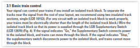
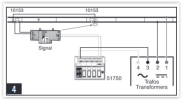
Does this (from the LGB instruction leaflet) help you . . .

1689262684392.png
1689262716254.png

Best wishes

David
 
Am I being thick, or isn't a passing loop on just one side of the oval all you need to run two trains? With a passing loop on both sides of the oval, you can operate three trains (but not one-and-a-half in each direction!), there always being a clear run round the oval for one train while two others are parked up in the loops..

Ah! Having thought a bit more, and looking at your latest diagram, it seems you are only planning to equip one line of each pair with a signal/isolating section!
Yes, that's right (not that you're being thick!). The layout I'm taking to Kirkbean this year is smaller than usual and so the round-and-round bit is just a simple oval with no "wriggle" factor via crossovers or curves other than the end ones, so I decided that I would have traffic in both directions, but not at the same time! So basically, the passing loops act as train parks. The North Loop will be for a counter-clockwise running loco and the South Loop for a clockwise running one. I'll stop the train running at random at the loops to give a "station effect". (I have a piece of electronics which will stop a loco at a set place every second or third circuit which I may use if I can remember how to set it up and find the bits to do so). There will also be a couple of shuttle lines running, usually there is only one, to add to interest.
Do you already have these? A friend who has just dismantled their garden railway has five of these for disposal (and I've offered to help him find new homes for them). I collected them yesterday but am yet to check that they work as they should.
Well, I have four, but I may be tempted to buy another two. Do they come with the isolating tracks or just the signals with drives and supplementary switches?
Does this (from the LGB instruction leaflet) help you . . .

View attachment 315837
View attachment 315838

Best wishes

David
I have some instructions, but I must say yours seem clearer to understand; the one I have has a misprint in the connections between the transformer and the switch box and though this is pointed out it is a distraction to the non-electrically minded like me. Many thanks for that.
 
You talk about isolating points and LGB signals, I believe the signals come with a short isolating section thus points at the signal end would not need to be isolating. I assume you will be modifying LGB points (or whatever brand you will be using) to be isolating in this scenarion. However with a signal at one end the circumnavigation of that loop would be that loop would be expected to be one way.
 
You talk about isolating points and LGB signals, I believe the signals come with a short isolating section thus points at the signal end would not need to be isolating. I assume you will be modifying LGB points (or whatever brand you will be using) to be isolating in this scenarion. However with a signal at one end the circumnavigation of that loop would be that loop would be expected to be one way.
The signals used to come with a 150mm length of normal track and a half length split section and an auxiliary switch, but now you just get the signal for about £110; fortunately, I bought my four off eBay, boxed and complete with both bits of track and auxiliary switch. The last one I bought in October 2021 cost me £76 including p and p!

All trackwork is LGB, as are point motors and the layout is as you suggest - "the entry to the loop will be controlled through an electrically operated point connected to a 1015U split track. The exit side will have an electrically operated point and an electrically operated signal, the signal at stop being the means of isolating the train from the exit end through a1015U split track and from the entry end similarly".

EDIT: An idea has just occurred to me - could that auxiliary switch on the signal be used to operate the exit point? I think it could
 
Last edited:
The signals used to come with a 150mm length of normal track and a half length split section and an auxiliary switch, but now you just get the signal for about £110; fortunately, I bought my four off eBay, boxed and complete with both bits of track and auxiliary switch. The last one I bought in October 2021 cost me £76 including p and p!

All trackwork is LGB, as are point motors and the layout is as you suggest - "the entry to the loop will be controlled through an electrically operated point connected to a 1015U split track. The exit side will have an electrically operated point and an electrically operated signal, the signal at stop being the means of isolating the train from the exit end through a1015U split track and from the entry end similarly".

EDIT: An idea has just occurred to me - could that auxiliary switch on the signal be used to operate the exit point? I think it could
Yes it will, much of that is pretty well as used in EPL automation.
 
Am I being thick, or isn't a passing loop on just one side of the oval all you need to run two trains? With a passing loop on both sides of the oval, you can operate three trains (but not one-and-a-half in each direction!), there always being a clear run round the oval for one train while two others are parked up in the loops..

Best wishes

David
With one passing loop you can have two trains, but only run one at a time in opposite directions, otherwise when both trains get to the opposite side of the oval they crash.
 
Back
Top