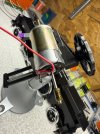
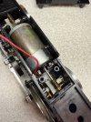
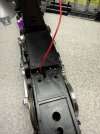
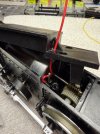
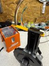
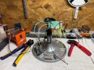
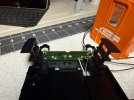
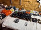
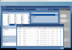
LGB 2044 RhB Class Gea 2/4 Electric Loco, conversion to LGB 55029 decoder

POLO_Train

Registered
Country flag
Hello all again,
I am started my LGB 2044 RhB Class Gea 2/4 Electric Locomotive conversion to DCC with an LGB 55029 decoder.
I have read and heard that there are better decoders on the market, but I shotgun purchase a few LGB 55029 to digitize my collection. I had posted a few pictures and questions in my past posts, but I hope I can open a new thread to show to work through any pain points to convert the 2044 to DCC with the LGB 55029 mfx decoders.

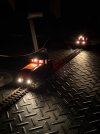
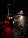
I checked the engine lights how they worked in analog.
The lights worked liked this:
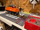
IMG_0073.jpeg and like this: IMG_0074.jpeg

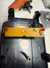
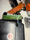
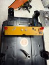
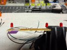
The front and rear lower lights PCBs (x2) look like this:
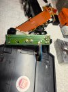
IMG_0021.jpeg and IMG_0022.jpeg

I removed the diode, resister, and one more component to rewired them to have two positive inputs and one negative output:
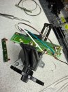
IMG_0083.jpeg

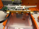
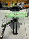
I moved to the upper PCB for the top front, rear, and cab lights (plus catenary wire) are wired to the board.
Top: IMG_0016.jpeg and the bottom: IMG_0017.jpeg' before I modified the board.
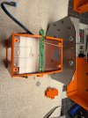
I removed the two diodes. Then I tried to figure out a way to run all the wires through the front top light housing. I reused the top centenary solider point to jump to the rear light. I also solder the 3 wire to the negative, positive as well:
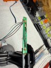
IMG_0075.jpeg
Then I solder in new wire to the front light "Bulb block" (I am guessing) to create its unique positive:
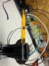
IMG_0076.jpeg
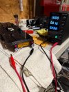
I tested it all and it worked well in current 4 wire configuration:
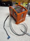
IMG_0078.jpeg

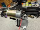
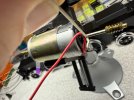
The motor block is a 3 wire motor block. I was trying to figure out a way to wire in a new post to create 4 wire block.
I was not able to figure out a way it would work well without shorting out the motor.
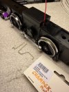
IMG_0097.jpeg

I do not have the drill press that has the accuracy to do it within a 1mm.
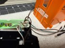
I solder in the wire to the motor lead and drill in an output into the plastic above it:
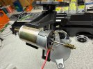
IMG_0089.jpeg and covered it up: IMG_0090.jpeg and shrunk it; IMG_0091.jpeg and it fit well in the motor block: IMG_0094.jpeg and it all closed up: IMG_0096.jpeg

I need to wait for the 24V Red LEDs to arrive, so that I can wire the front and rear PCB wire leads to the decoder.
Then I will put the 2044 back together and start editing the program and figure out how the white and red lights work together.
 

Attachments

  • IMG_0098.jpeg
    IMG_0098.jpeg
    469.7 KB · Views: 0
  • IMG_0092.jpeg
    IMG_0092.jpeg
    670.6 KB · Views: 0
  • IMG_0079.jpeg
    IMG_0079.jpeg
    534.5 KB · Views: 0
  • IMG_0085.jpeg
    IMG_0085.jpeg
    530.2 KB · Views: 0
Great guide / write-up.

You know, I've converted a lot of older LGB locos (mostly split gearbox) and I feel rather dumb having never soldered the wire vertically from the motor contact. I always go horizontal and then up .

Btw, I love the stand you used to hold the motor for soldering. Where did you get it?

When I digitised my V51, I used bi-colour LEDs (white/red) (like these) on the red LEDs. You can then wire the two anodes to the LV / light front and LH / light back contacts on the decoder and use the decoder's inbuilt directional lighting.
 
Excellent write-up, but I hope an error in your typing?

DCC uses a common positive and the individual light and function outputs switch the negative.

You did not need to buy new LEDs, as you could just fit different resistors. - A LED is a LED, after all.

In the past, I have unsoldered LEDs, and turned them round, to reverse the polarity of the common connection.
You do need to be aware of any diodes that are also in the circuit, and if there are a mixture of bulbs and LEDs, then you can get 'strange' results.

Well done so far.

PhilP
 
Great guide / write-up.

You know, I've converted a lot of older LGB locos (mostly split gearbox) and I feel rather dumb having never soldered the wire vertically from the motor contact. I always go horizontal and then up .

Btw, I love the stand you used to hold the motor for soldering. Where did you get it?

When I digitised my V51, I used bi-colour LEDs (white/red) (like these) on the red LEDs. You can then wire the two anodes to the LV / light front and LH / light back contacts on the decoder and use the decoder's inbuilt directional lighting.

Thank you!
I am definitely going to looking into those LEDs.

The vise is PanaVise and love it, and I allows recommend that brand:
 
Excellent write-up, but I hope an error in your typing?

DCC uses a common positive and the individual light and function outputs switch the negative.

You did not need to buy new LEDs, as you could just fit different resistors. - A LED is a LED, after all.

In the past, I have unsoldered LEDs, and turned them round, to reverse the polarity of the common connection.
You do need to be aware of any diodes that are also in the circuit, and if there are a mixture of bulbs and LEDs, then you can get 'strange' results.

Well done so far.

PhilP
Thank you!
I did forget that and I didn’t know that with the leds and decoders.
I did order replacements, because I did think I damaged one testing’s them out.
I bought these:
 
Thank you PhilP PhilP for the additional information, I did not realize the decoder way positive common. I think all the lamps will be okay but the Red LED lights will not be okay. I think I burnt one out while testing and hopefully I replace them on Tuesday or Wednesday, so that I can wire the 2044 engine up to the LGB 55029 decoder.

I had a few free hours to push forward the conversion.

Thank you again to everyone, I solder the decoder base PCB and the cab lights PCB with a heat treatment the wires to curve the wires so that they will fit better into the front of the loco.

IMG_0104.jpeg

I did heat shrink them as well:

IMG_0106.jpeg

IMG_0107.jpeg

My next steps will be to be determine how to solder in the new Red LED/Lights so that they will work well with the decoder.
I believe it will be simple and not a big issue, but I wish to swap out the solder in LEDs from the 1990s.

I think if I swap the wire between AUX1 and AUX2 connections with the front and rear of the small PCB, they will function just as the analog version of the 2044 based not the downloaded coding from the Marklin server code without of me having to edited the code.

I am still very new to all of the DCC. I did burn out at least one LED when pushing them during testing the LEDs.
My passion for collecting was to do a full analog layout with the LGB jumbo transformer. I need to sell the old jumbo controller, ha.
 
Excellent write-up, but I hope an error in your typing?

DCC uses a common positive and the individual light and function outputs switch the negative.

You did not need to buy new LEDs, as you could just fit different resistors. - A LED is a LED, after all.

In the past, I have unsoldered LEDs, and turned them round, to reverse the polarity of the common connection.
You do need to be aware of any diodes that are also in the circuit, and if there are a mixture of bulbs and LEDs, then you can get 'strange' results.

Well done so far.

PhilP

I am not sure how to go about getting either the existing 3v LEDs to work with the the existing front and rear light PCBs.

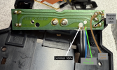
First, the front and rear LED lights are soldiered in two different orientations.
The Front board has the positive leg on the inside, and negative leg on the "common" outside bus.
The Read board has the negative leg on the indside, and the positive leg on the "common" outside bus.
IMG_0108.jpeg
(Front Light PCB is on the left)

Now my confusion starts with the 55029 decoder being 18V+ common, as PhilP PhilP nicely pointed out to myself.
I believe the original Analog setup has used the positive bus on the right (I do not have anything wired to it) and a negative common bus back.

My first attempt I do not think it will work with LED lights:

IMG_0113.jpeg
(Not my best solider job, but it works haha).

Here is the board before I removed anything:

IMG_0021.jpeg

And the other side:
The resister I believe is a 270 Ohms at 5%

IMG_0022.jpeg


I am not sure how I will accomplish the wiring with the existing PCB buses with the common being on the outside bus.
I think I can jump the LED "inside" bus back to the original blue wire bus with a 800 ohm resistor (330 + 470 resistors in series)?

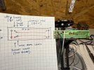
I am guessing, but this is my best guess:Light PCB Edited_50.png
 

Attachments

  • IMG_0109.jpeg
    IMG_0109.jpeg
    857.8 KB · Views: 0
  • IMG_0110.jpeg
    IMG_0110.jpeg
    752.1 KB · Views: 0
  • IMG_0115.jpeg
    IMG_0115.jpeg
    751.6 KB · Views: 0
Last edited:
Yes, you will either need to add resistance, or you can can alter a CV to set a 'divider' to reduce the apparent voltage..

Now, you will have 'front' and 'rear' lighting outputs on the decoder.
These are usually labelled 'LF' or 'LV' for 'front' and 'LR' or 'LH' for 'rear'.
But.......
The Front output is 'on' when going forwards, and the Rear output is 'on' going backwards.
This means if you want a rear red light 'on' when going forwards, you have to connect it/them to the 'front' light output, along with the front white headlight.

Just something else to catch you out the first time you do this.

You should not need the diodes that are on the lighting boards.
If you are using a decent value of series resistor, you should not 'pop' a LED if you get the polarity wrong. - It just won't light up.

The best you can do is have a 'play', which will teach you more than my trying to get it right from here..

PhilP
 
Thank you again PhilP PhilP

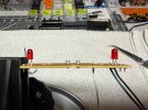
The 800 Ohm worth of resistors in series worked well on the rear red LED lights and they also cleared the steps.
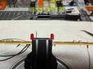
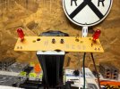
Here are the pictures of the rear lights PCB fitting back into its place and ready to be hooked up to the decoder.

IMG_0119.jpegIMG_0118.jpegIMG_0116.jpeg

More 5mm LEDs show up Friday so that I can complete the front lights PCB and get it all put together this weekend!
 
The 55029 adapter boards have 3 solder pads for the LV (front) and LH (Rear) connections. what you do is wire the negative from the front headlights and rear red lights to the LV and then the rear headlights and front red lights to the LH. Thats how you easily get them to come on in the proper fashion without any other programming.

I used 3V WW leds for headlights and 2V red LEDs on my 2044. This is why I use a buck converter to drop the voltage from one of the AUX terminals on the 55029, the dedicated 10V output on a 5 XL decoder, or the dedicated +/- on Massoth emotions or Soundtraxx Tsunamis. Dealing with full track power and dimming outputs doesnt always work well and I got flicker with a 55029 trying to do that. I set the buck converter to 3V and then use resistors on the light board for the red LEDs. I think I only needed a 36ohm resistor for the 2 red LEDs in series.

With the 55029 with a buck converter you then need to assign that AUX terminal to the light functions so the power comes on to the buck converter. All positive leads for the LEDs get connected to the positive from the buck converter and the negatives all go their respective terminals on the decoder.

Thank you Diesel,
I did go with 2V diffused Red LEDs off of amazon. They are much brighter than the originals while testing with the testing PSU.
I swapped out all four with the new Red LEDs and I do like the extra brightness compared with the 24V warm light bulbs.
The front PCB did need the LEDs flipped anyways to work with the existing PCB.

I ended up using 800 ohm of resistors instead of a buck converter, and that does run the LEDs well.
The 55029 does flicker a little bit, I did see that too while test running the engines.

I did get it all wired up today. I do need to shorten some of the wires and drill out a speaker grill location for it, but it works for now.

IMG_0147.jpeg

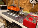
Also, I got it put back together, and put on the tracks with the 2046.

IMG_0155.jpeg
IMG_0152.jpeg


It is working well with it back together. I started to mess around with the configurator.
I started to modify the parameters for the motor and get it to match the 23101 engine. It runs well with the config, and I really am enjoying the CS3 with the decoder software, and running the trains on the laptop or on my phone.

I did add a marking light function to have only the red LEDs on to simulate engine is stationary. I don't know if that is prototypical, but I do like just the Red LEDS on while it is not running/stationary.

I do not think there is too much to do else now for the 2044 besides tiding up the wiring a bit more and making a better speaker location with holes.

Thank you all again for all the help!
 
Thank you Diesel,
I did go with 2V diffused Red LEDs off of amazon. They are much brighter than the originals while testing with the testing PSU.
I swapped out all four with the new Red LEDs and I do like the extra brightness compared with the 24V warm light bulbs.
Yes, swapping to new 2V red diffused dome LEDs are much brighter than the originals. I get a little nervous with the heat that large resistors produce trying to drop track voltage down so much, which is why I light to use buck converters and full power to the outputs. Because there are no dedicated +/- terminals on the 55029 its a little harder to configure. It does matter what track voltage you run at with resistors as there is a noticeable brightness difference at 18V vs 24V. On factory MSD3 boards I add resistors, but those outputs are already dropped to 6V, so can use much smaller resistors.

Looking good, nice job.
 
P POLO_Train I just had a look through the manual. You should be able to dim (reduce the voltage) of the output so you don't have to worry about adding a buck converter.

I've not used this model before - however, from experience with similar decoders I suspect that CV 113 and 117 (Front and Rear) are the dimmable value. If you read the CV now, I expect it to be 255 which is 100% of track power (so ~20V). If you set that 128 (about half), I suspect you'll get 50% of the voltage.

If you need ~2V (and you're running 20V on the track), you need about 10% of the output (2V / 20V) then multiplier by 255 to find the int value.

I'd recommend doing the following:
  • Disconnect your lights from the decoder.
  • Read the current value of CV113 - write this down (I'm guessing it is either 255 or 190)
  • Turn the lights on (F0), measure the voltage on a multimeter (I'm guessing you'll get ~18-24V)
  • Set the value of 113 to '25'.
  • Turn the lights on, measure the voltage on a multimeter (you should get ~2V)
Make sure you do this before connecting any lights back up so you don't blow what is attached (speaking from experience).
 

Attachments

  • Screenshot 2025-01-06 at 14.34.49.png
    Screenshot 2025-01-06 at 14.34.49.png
    299.5 KB · Views: 0
Last edited:
Did you get (at least) some of the weights back into the lok? - They make a big difference to traction, and what it can pull.

PhilP
Yes sir, they were sitting right next to the engine ready to be installed once I figured out the wire routing.
 
P POLO_Train I just had a look through the manual. You should be able to dim (reduce the voltage) of the output so you don't have to worry about adding a buck converter.
Dimming does not work well with LEDs. Its fine for incandescent bulbs, but for LEDs you tend to get flicker with the 55029. I've tried both ways and find that the buck converter or resistors with full power to the light output is far superior with LEDs.
 
Diesel2000 Diesel2000 I just had a look through the manual. You should be able to dim (reduce the voltage) of the output so you don't have to worry about adding a buck converter.

I've not used this model before - however, from experience with similar decoders I suspect that CV 113 and 117 (Front and Rear) are the dimmable value. If you read the CV now, I expect it to be 255 which is 100% of track power (so ~20V). If you set that 128 (about half), I suspect you'll get 50% of the voltage.

If you need ~2V (and you're running 20V on the track), you need about 10% of the output (2V / 20V) then multiplier by 255 to find the int value.

I'd recommend doing the following:
  • Disconnect your lights from the decoder.
  • Read the current value of CV113 - write this down (I'm guessing it is either 255 or 190)
  • Turn the lights on (F0), measure the voltage on a multimeter (I'm guessing you'll get ~18-24V)
  • Set the value of 113 to '25'.
  • Turn the lights on, measure the voltage on a multimeter (you should get ~2V)
Make sure you do this before connecting any lights back up so you don't blow what is attached (speaking from experience).

Thank you Curtis,

I used 24V bulbs and resistors so that I did not have to test the dimmer function while just learning everything else with the decoder and the software. Now after two engines and playing with the software I wish to give that a try.
I do want to add a light to the FO engine room since there is space and windows. I can add a function for "engine room lighting" with output 4 dimmer down to 25 to test a 5V bulb.
I will hopefully be able to test that later this week!

LGB 2046 21 FO Configure - Engine Room Output 4 Setting to 25.png
 
Back
Top