Lift Bridge Design Question

Madman

Registered
Country flag
I am in the process of building a lift bridge for my Lionel "O" gauge layout. It will connect two peninsulas. It will rise from table top to a height that a person can walk under. I'd like to install limit switches so that when the bridge reaches its upper or lower position, it will stop, even if I have my hand on the DPDT momentary switch.

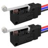
I have several of those tiny roller switches, similar to these.....71dstPrFBKL._SL1500_.jpg
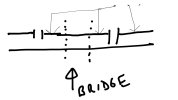
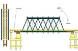
The bridge design, rough sketch.....

IMG_9142.jpeg

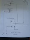
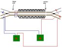
And the start of a wiring diagram.....

tempImageP32MCK.png

I need to complete the wiring diagram, but am stuck.....Please help !
 
Ok so you only need a dead section on 1 rail. Just 2 of the contacts need to be used, centre one for power then whichever one makes circuit for the other. A wire from that needs to go to each side of the bridge to a dead section long enough to stop the fastest train. When the bridge is in place for trains the circuit will be made by the bridge pushing the roller, when out of place one rail either side will have a dead section.
IMG_8356.jpeg
 
Last edited:
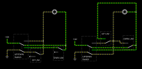
your sketch has all the required components but none of the connections. I've sketched this circuit with the bridge halfway and neither the top or bottom switch opened. The dpdt switch will be able to send the bridge either up or down until it reaces the relevant limit switch. When it reaches that limit switch it will stop going any further but the circuit for the reverse direction is ready to go.
Personally I dont think that you need a momentary dpdt switch. A normal dpdt switch would be easier, then you can flick the switch and let the limit switches do their job.

Alan


IMG_20250107_110725774.jpg
 
your sketch has all the required components but none of the connections. I've sketched this circuit with the bridge halfway and neither the top or bottom switch opened. The dpdt switch will be able to send the bridge either up or down until it reaces the relevant limit switch. When it reaches that limit switch it will stop going any further but the circuit for the reverse direction is ready to go.
Personally I dont think that you need a momentary dpdt switch. A normal dpdt switch would be easier, then you can flick the switch and let the limit switches do their job.

Alan


View attachment 337183
I think you are missing the point re the momentary switch. My diagram stops inadvertent trains passing over and onto the ground when the bridge is open, all too easy to do if distracted.
 
Jon I think we have crossed tracks :) My suggestion was for the bridge lifting circuit.
I totally agree that there must be dead sections of track approaching an open bridge. This could be implemented by using a micro switch that only passes power to the dead approach sections when the bridge is fully down as you suggested.

Alan .
Sorry my mistake, automatic lifting could be a tricky solution due to weight of the bridge in our scale but be interested to see if it occurs.
 
I'd like to install limit switches so that when the bridge reaches its upper or lower position, it will stop, even if I have my hand on the DPDT momentary switch.
this kind of bridge needs vertical rails to move.
use that for the steering mecanism.
on one side make the uppermost part of the rail from plastic. on the other side the lowest part.
the motor (on the bridge itself) fed through one of the vertical rails from a double throw switch for "up". the bridge reaching the plastic part of the rail, the motor stops.
through the other vertical rail you connect the motor to the switch with the opposite polarity.
when you change the switch, the "downwards"rail (with the plastic rail part below) gets current. - till it gets to the lower plastic section.

= a foolproof system. it can't go too far, it can't go "back" without operating the switch. the most sophisticated electronics needed, is a doble-throw switch.
(regardless, if you use cog-rail or cable for lifting)

the other thing in this thread - security against trains driving into the open gap.
easy peasy - just make a two trains long block with the bridge in the middle, feed the positive cable to the right side of the bridge, and the negative cable to the left side of the bridge. use the track on the bridge to connect the two sides, when it is in place.
that's hill billy safety 1.01

disadvantage: that works only with analogue DC - welcome to hill-billy world!

As my design moves forward, on paper for now, the thought of the counter weights blocking the tracks when the bridge is up appealed to me. Talk about hillbilly simple.....;)
 
As my design moves forward, on paper for now, the thought of the counter weights blocking the tracks when the bridge is up appealed to me. Talk about hillbilly simple.....;)
Hm only when fully down, depending on how high you lift the bridge an unexpected train may sneak up before the counter weight is down?
 
a catch point either side of the bridge that is switched when the bridge is raised?
Thus possibly diverting the loco off the board? A simple switch as earlier described with a dead section either end is by far the simplest of systems. As soon as the bridge is moved the sections go dead thus stopping a train. Sometimes I think we over think what is a simple thing, ending up making things so complex that paralysis results.
 
Surmising electric motors driving screw threads (like a 3 D printed Z axis) are being used to raise and lower that bridge since a DPDT throw switch is mentioned.

Food for thought.
To simplify the operation of the bridge could a simple hinged bridge be use instead.
Then the switches could be used to remove power from the track when opened by simply mounting one under each end of the bridge.

How wide is the opening? A 3 foot wide opening should be more than sufficient to allow passage of people.

This how I did mine it is just under 1 meter wide, wide enough for me to push a wheelbarrow through.

The hinge design came from Korm Kormsen and is what I am using for a further 4 bridges on my reconfig project, been working with no issues for 5 years

Korms Bridge.jpg
 
well, that lift-bridge was originally planned as a "gauntlet"-bridge. it is about four foot long.

btw: that only works well with diagonal cut rails - as marked in the pic above.

here is, how i prepared the safety shut-off:

safetycircuit.JPG

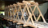
due to a change of plan (from one level with access to two level with duck-under) it ended as ordinary one-track trussbridge for bumping my head.

bruecke1-20.JPG
 
Back
Top