Massoth 4 channel switch Decoder

Graham

In Smoggy Land
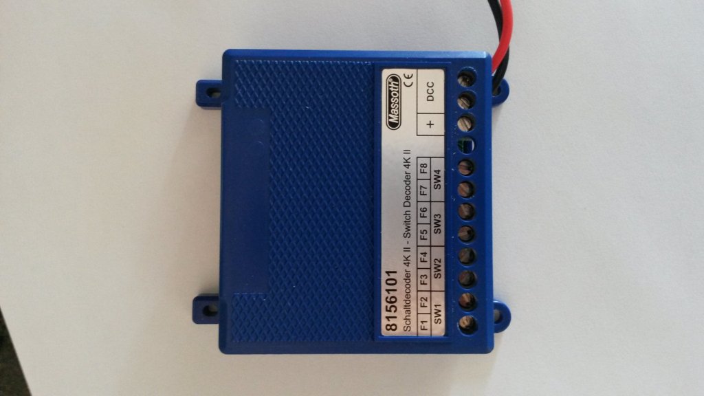
Hi Folks some help please. I'm sure the Massoth stuff is the bees knees but their ability to produce clear manuals is rather less great. So I have ended up with some or the 8156001 and the new version 8156101 of the 4 channel units. I intend to operate these by using switches in a mimic board (as well as via the the DCC control). My confusion is around the external switches needed to trigger the device. On the earlier version the picture given in the manual (page 8) would appear to show one common leg being closing onto the other two, i.e. not a changeover arrangement.

upload_2016-7-14_20-19-47.png
On the new version the drawing appears to show a changeover switch centre off (I don't have an electronic version of this ones manual)?
Can anyone enlighteen me?
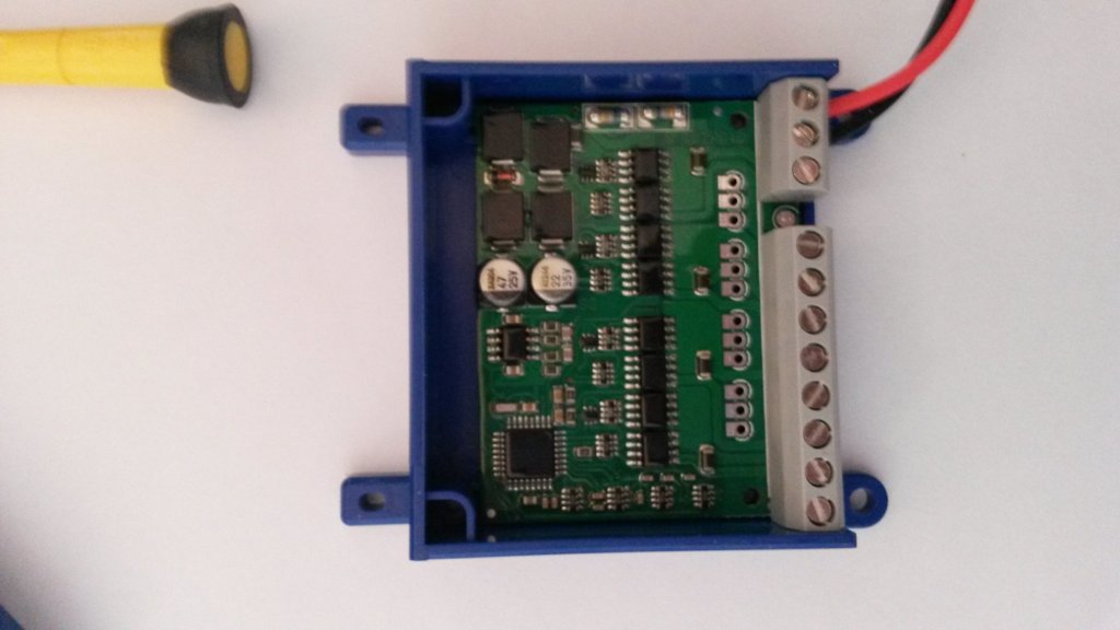
I also note that on the new version the switch connections are internal and require to be soldered onto the PC board!!
 
The diagram in the new manual is effectively the same as the old. Each contact pair shown are two switches with one common connection.
4KII_contacts.PNG
 
I don't have one of these so no idea about space in the casing nor the pitch of those solder pads etc., but if possible I'd be looking to solder suitable 3-pole header pins to accept plugs - preferably the latching type as discussed recently in another thread.
 
They have a screw terminal block. Each is quite close together pitch wise.

I think Muns diagram is the underside.

Not got mine to hand at the moment (working away) so I can't comment any further atm....
 
They have a screw terminal block. Each is quite close together pitch wise.

I think Muns diagram is the underside.

Not got mine to hand at the moment (working away) so I can't comment any further atm....

The previous version had screw terminals that were external, the new version has just the solder pads and they are internal. The big difference between the two versions was the previous one if you wanted to use switch activation you could only have three outputs. The new version can utilise all four outputs, but as a result it looks like they did not have enough space to go the external screw terminal root. I will do some measuring to see if I can fit solder pad screw terminals as there should be enough depth in the case. The issue maybe how to get the wires to the outside of the case without drilling it full of holes :mad:
 
The previous version had screw terminals that were external, the new version has just the solder pads and they are internal. The big difference between the two versions was the previous one if you wanted to use switch activation you could only have three outputs. The new version can utilise all four outputs, but as a result it looks like they did not have enough space to go the external screw terminal root. I will do some measuring to see if I can fit solder pad screw terminals as there should be enough depth in the case. The issue maybe how to get the wires to the outside of the case without drilling it full of holes :mad:
That's a new one on me Graham?

The ones I was helping a mate with recently had the screw terminals. I've haven't seen one with solder pads yet?

A backwards step I reckon, as most people would prefer the terminal option....
 
The diagram in the new manual is effectively the same as the old. Each contact pair shown are two switches with one common connection.
View attachment 212987

The problem for me is that while the new one looks like a momentary SPDT the older version could be anything and neither are standard forms for indicating switches! Anyway I agree that it will need to be a SPDT momentary switch...suitable switches ordered previous ones gone into that big box marked "spares for future projects" :devil: which is getting quite full ;)
 
That's a new one on me Graham?

The ones I was helping a mate with recently had the screw terminals. I've haven't seen one with solder pads yet?

A backwards step I reckon, as most people would prefer the terminal option....

I have to agree it does make things much more difficult and not everyone is confident to solder onto small pc boards like this. With a bit of adjusting the layout I'm sure there is enough space in the case to have had screw terminals at the opposite side of the case. Anyway it looks like I will have to some butchery :banghead:
 

Attachments

  • 20160715_131250.jpg
    20160715_131250.jpg
    63 KB · Views: 0
  • 20160715_131520.jpg
    20160715_131520.jpg
    61.4 KB · Views: 0
In passing is there a thread about programming a 4 channel switch decoder, I have 4 units and I want to change their numbers. I have the Massoth Dimax PC module and have downloaded the MST service tool but can' understand which template I should use :(
 
In passing is there a thread about programming a 4 channel switch decoder, I have 4 units and I want to change their numbers. I have the Massoth Dimax PC module and have downloaded the MST service tool but can' understand which template I should use :(

Re MST, your picture above shows a 8156101 4K II switch decoder, this is the latest reincarnation of the original 8156001 switch decoder, both decoder templates are present in MST, both are dated 12/05/2016 as being the latest versions of the templates.

The electronic version of the 8156101 can be located here:
http://wiki.massoth.de/images/6/64/991087_BDA_8156101_2016_06.pdf

8156101.PNG
 
Last edited by a moderator:
I have to agree it does make things much more difficult and not everyone is confident to solder onto small pc boards like this. With a bit of adjusting the layout I'm sure there is enough space in the case to have had screw terminals at the opposite side of the case. Anyway it looks like I will have to some butchery :banghead:
On the other hand on the earlier model the screw connections were quite small and difficult to fit decent sized wire (like 24/2). The new one is more like the LGB accessory decoder, with large screw connections and only 12 of them, 8 for the 4 point motors, 2 for DCC and 2 for programming. As I don't use the manual switch option I'm happy with the new design although I appreciate it makes it more difficult for those that do. The best design would have been to have 12 screw connections as above and on the reverse 12 screw connections for 4 x manual switches, although this would probably make the device bigger.
 
Is it this one MAS_DIMAX_WEICHEN_002?


8156001 = MAS_DIMAX_WEICHEN_000
8156101 = MAS_DIMAX_WEICHEN_003

Latest version of the Massoth Service Tool is 2.1, build number 2.1.27.0 dated 15/07/2016, available to download via the Online Update, to be found under the heading General.
 
8156001 = MAS_DIMAX_WEICHEN_000
8156101 = MAS_DIMAX_WEICHEN_003

Latest version of the Massoth Service Tool is 2.1, build number 2.1.27.0 dated 15/07/2016, available to download from Massoth Wiki.

Thanks, through a bit of trial and error found the right one. Once I had that along with the PC module I managed to change the addresses on 3 of the 4 switch decoders in 10 minutes :rofl: so now they go from 1 to 16. I also aquired the new Massoth service board so played with two old and one new LGB loco decoder using the MST and it was a breeze. The only thing that puzzles me is the manual for the switch decoders mentions CV 15 and 16 being some sort of lock. However these numbers do not show up in MST :( am I missing something (apart from a few screws :confused::confused:)
 
Ah! The joys of the Massoth Manuals, in most cases are best used as a visual aid, only effective method to see what is going on is to use the Massoth Service Tool!

The 8156101 uses CV15, putting a value of 0 activates the lock, a value of 243 deactivates the lock. CV 16 automatically changes to reflect the value in CV 15.
By default CV15 and CV16 are set to 243.

And, just to make life more interesting, on the 8156001, the decoder lock uses CV2 with values of 0 and 77.
 
Last edited by a moderator:
In the MST, CV15/16 are hidden and CV15 can be changed by using the Programming Lock control...
4KII_MST_lockPNG.PNG
 
Hi all,

Can I connect an external power supply negative to the central solder pad of one of the contact inputs so as to drive LED signals from the external positive and not the decoder positive. I want to reduce the load on the central station
AVR
 
The load of Massoth 4-way switch decoder is 30mA.. If you are switching LED's, then their current consumption will also be trivial, in comparison to the ability of your CS to supply current.

If you are close to the total current-loading of your CS, I fear you need to look to a booster.
 
Back
Top