Piko 35013 Switch decoder confusion

NDC

Registered
Country flag
HI, I've acquired a couple of these from different sources and started to play about with them. I connected up the first and it switched over an old LGB 2-wire motor perfectly. 10 mins later I happed to touch the motor and it was hot. It transpires that the controller switches the polarity to the motor but doesn't switch off after the pre programmed time interval. Fiddling around with CVs, I found the values of 51 to 58 are all 67 (0.75 seconds pulse duration). So is there another place to tell the controller it needs a pulse and not continuous power?

Strangely, the 4th position works perfectly..... The second unit is identical so I suspect the common failure for these two is me.

Thanks
Nick
 
Have a look here....

 
Thanks, I did notice that thread. I can manage to set the CVs OK but it doesn't respond as I think it should.
 
I'm not familiar with the Piko decoders. On LGB switch decoders, you can set the point motor timing pulse for up to 0.75 sec from memory?

It seems like some of your outputs are not pulsing but are permanently off or on, maybe to drive a colour light signal?

Anyway, I did a Goggle search for Piko 35013 Instructions and found this....

 
Thanks, I've been following the instructions and varied the pulse time settings, all to no avail sadly. I can reset the system and the motor shuts off, but not really practical!
 

No mention of which DCC system used?

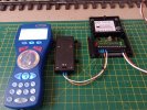
Presuming that the following setup as in the picture below is used to Write and Read CV's?

Programming Link, shown as Black wire.

Point Motor, Orange and White wires to Port 1.

Brown and White wires to DCC System PROG.

Port Address 32, 34, 36, & 38 set at x, where x = value of 1 - 2048 either sequentially or non sequentially.

Output Function 51, 52, 53, 54, 55, 56, 57 & 58 set at n, where n = value of 65 - 79, default 67.

The only CV so far not mentioned is CV49 which should be set to 0 as in default value, although probably irrelevant as Port 4 appears to work correctly.

PIKO 35013 Decoder Setup.jpg

Referring to the what appears to operating correctly as Output or Port 4.

Use as a testing point, as a reference to establish and verify the correct operation of the remaining three Ports.

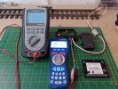
With the aid of a Multimeter, which will verify whether the Port is working correctly or not, as in the picture below, when the Port is idle, no voltage is present.

When the Switch decoder is activated, either a Positive or Negative value will appear on the Multimeter screen, (Massoth System shows +21.07V and -21.07V)

Then starting with Port 1 repeat the testing procedure, IF in the IDLE state a voltage figure appears, could be either POS or NEG, this indicates the Output(s) of the H Bridge controlling that particular Port have malfunctioned, assuming that the correct programming procedure has been followed as mentioned and shown at the beginning of this post, basically in a nutshell the Output Port is FUBAR!

Most likely and common cause for this failure is, operating TWO older style LGB Point Motors from ONE Output Port, the older style LGB Point Motors have a higher operating Amperage Rating, and two operating together, exceeds the power output of the H Bridge, result FUBAR!


PIKO 35013 Decoder Port Test.jpg
 
Last edited:
Back
Top