Recent 'bargain' purchase..Wangerooge diesel...non runner

Brixham

No buffers were hurt at this sign
Country flag
Bargain purchase at the recent 16mm show.....a near mint condition 060 diesel loco from the Wangerooge set...but a non runner...
I was told the motor works, no wear on the sliders, and the wheels looked unrun. So it came home with me..a simple fix maybe.
Especially as the power switch was in the 0 position. You never know....

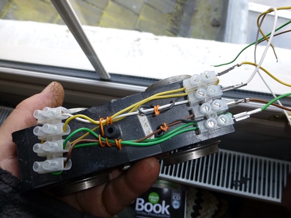
I had a look last night, a previous owner has half butchered the electrics....

Missing are both the springy busbars that connect the 3 bullet 'back of wheel scrapers' and the slider power pick ups.

The 4 way motor block connector is missing, and the outer wires ( motor? ) have been cut off at the pcb connector..circled in red
the inner wires are present, but end in bare leads

The cab switch has been pruned of all wiring, and a loop fitted to the connector where the switch plugs in..circled in orange

The set number is 70580, but I don't have a stock code for the loco. There are similar locos, 20590 and 21590, which I need to search for the wiring diagram....I didn't spot one in a quick browse through champex

The busbars I can probably make, copying from a similar motor block. Today at work I separated the motor block connector, and inserted new wires, and reclamped it. I found some push on connectors from LGB ball bearing wheels which I can solder to the bare ends, and then have a go at powering the loco up.

I'm not too bothered with re-instating the switch, as this is something I never use.
I use analogue, as long as the loco runs, and the lights work according to direction, I'll be happy.

Malcolm
 
I am assuming the 4 way connector is the black push in connector for the motor block, I have one that I has a 5v light circuit board piece as well, came of an analogue Stainz I have converted to digi, I cut the wires with approx. 3/4 inch left attatched.

Yours FOC, if you want it, just drop me a PM with your add and ill bung it in the post.
P1000746 (600 x 400).jpg

Plug is only soldered to the board so can be removed if you just need to connect the four wires..


Thanks...PM on it's way....

I think clearance is a bit tight, so the way to go is remove the board, and solder direct to the connector pins

Temporary test lead now constructed

malcolm
 
Bit is now packed and ready to post tomorrow :D
 
Hi Malcolm

If the spare board from a Stainz you've been promised doesn't work, I have a complete new main board for the Wangerooge including the switch should you need it. By the way, in analogue the board does not work without the switch plugged in (unless you short the correct terminals.....).

You'll still need a connection from the board to the motor/track pickups, but I may have one of those squirrelled away somewhere.

Let me know if I can be of assistance. :D
 
whatlep said:
Hi Malcolm

If the spare board from a Stainz you've been promised doesn't work, I have a complete new main board for the Wangerooge including the switch should you need it. By the way, in analogue the board does not work without the switch plugged in (unless you short the correct terminals.....).

You'll still need a connection from the board to the motor/track pickups, but I may have one of those squirrelled away somewhere.

Let me know if I can be of assistance. :D

See despite what everyone says, Peter is a real gent :D :D
 
Quick update, with my temporary motor block to 'red circled' connector lead.....only the lights work, either front or rear depending on which way the controller is set. The loop wire replacing the switch must be the issue...0 would be off, 1 for lights only, and 2@3 lights and motor. The loop wire is shorting the middle two pins on the 'orange circled' switch connector
More investigations tonight.
Stupidly, I should have brought the loop wire into work, and maybe shorted all 4 pins together. Easier at work, as we have a bench vice to close the connector. But I do have a small hand vice at home.
There you go..many vices!
 
3Valve said:
See despite what everyone says, Peter is a real gent :D :D

(Panto mode on)
O no I'm not!
(Panto mode off)
;D
 
Switch to connctor lead...??? Query

Peter..could you look at yours....

On the switch pcb there are 4 solder pads for the wires....these go to the corresponding 4 terminals in the plug...but which way round?

In the loco the switch solder areas are towards the roof, and the wireing solder pads beneath them. Does the wire which would be closest to the centreline of the loco, go to connector terminal nearest the edge of the board..or the centre?? And then in sequence

Maybe a picture of your lead would help..and you do have my work address!

Malcolm
 
Brixham said:
Switch to connctor lead...??? Query

Peter..could you look at yours....

On the switch pcb there are 4 solder pads for the wires....these go to the corresponding 4 terminals in the plug...but which way round?

(snip)

Maybe a picture of your lead would help..and you do have my work address!

Malcolm

Malcolm - curiouser & curiouser! The switch which came with my board is only 3-position (presumably 0/1/2), but still has 4 wires running from it to the main board. I'll have to try to get a picture of the switch, but if you consider the screw hole on the switch to be "top" and read the wires from top to bottom, then the wires go as follows:
Switch top terminal = Board plug top wire (1 of 4 reading down from your picture)
Switch middle terminal = Board plug lowest TWO wires (3 & 4 of 4)
Switch bottom terminal = Board plug wire next to top (2 of 4)

By the way, did you get my PM about the signals?
 
Malcolm....

Just to let you know, plug and the other bit posted this afternoon, 1st class, so should get it tomorrow.
 
[attachimg=2]Just so you know, it is easy enough to jury rig an LGB 4 pin motor block by using the LGB tabs that come with Chips. Then you can make up 4 leads with correct LGB colour code:-
Track White and Black
Motor  Yellow and Green
This way you can play about to see that the Motor Block works OK. If all fails you can permanently  join up White to Black and Black to Green and the chassis should run when you have sorted out the Bus Bars and other Pick Up issues. At the very least you could put power to the Motor Yellow and Green to see if that is OK. Pic shows my Test Chassis with the Tabs shown connected to the Correct Colours on the Choc Strip. I use these Tabs to test out Chips by wiring them direct to the correct Pin Points on Massoth etc Type Chips.

Good luck with your cheepo Wanger Loco, they are great little runners.
JonD

[jattachimg=1]
 

Attachments

  • image.jpg
    image.jpg
    90.6 KB · Views: 24
<pedantic>
Normally Brown, not black..
And,
Motor + Yellow
to
Track + White,
Motor - Green
to
Track - Brown

But we get the idea..
;) :D :D
 
No progress since last update.....but after today I have a whole 4 days off! Two days to mess around in the garden whilst it's good weather, Sunday is an inside tidying day..which may spill over to Monday.

Thanks guys for the wiring details...I'll attempt wiring the switch sometime over Easter, 16/02 wire fits snugly in the connector holes, and crimps up nicely.
My switch is definately a 4 position, and the instructions for the 20590 state that it is 4 way

The motor block does run, but not well as without the busbars, only 1 contact is connecting. I have some phosphor bronze wire which I'll attempt to bend into a suitable shape. If it works, fine, and I'll look out for some strip p-b to make new busbars
Peter..how long ago was the PM re signals? I'll PM you anyway...

Malcolm
 
Brixham said:
Switch to connector block wiring....like this?

Yep - that's how mine looks.
Damn cold & windy in the Hills today, so perfect for a little light wiring mayhem! :D
 
Where did all the time over Easter go?
Tidying. Gardening. Visiting.

Only spent a morning on the loco.

I soldered together 4 phospor bronze wires, to make a busbar, then bent the assembly into a shape that seems to work well.
Cleverly, the picture shows that I have put one on the wrong way round, after it fell out. I only noticed when I came to re-assemble it

Also repositioned the U shaped silver wire which was attracted to the motor magnet, it now gives the centre wheelset suspension.

Malcolm

busbar.jpg
 
Thanks Nodrog1826....the connector and switch arrived....

The conector board is too large to fit between the chunky metal weight, so had to be cut. Also, there are tracks betwen the outer `rail` pins and the `inner` motor pins, so they had to be cut, circled in red. I did think about leaving them there, which would then remove the rquirement to re-instate the switch.

Next stage, fit the main board to the top of the weight ( there was&nbsp; a separate bag of bits, including plastic standoff spacers, now I know where they go ), and trim the motor block to 4 way connector leads, and resolder.
motor_block_conn_blobs.jpg
 
Absolutely....a bargain price!

But it's needed time to sort out..which I enjoy doing. So far it's cost nothing in bits, although I have had a donation of a motor block plug, and used up a quarter of a pack of phosphor bronze wires , ie about 50p's worth.

Of course, if you costed my time, it wouldn't be worth it.

The set new is/was? around £300, maybe more. How much is the loco worth?
 
Back
Top Bottom