Upgrading LGB DCC decoder to Loksound 5XL

Rjstruble

Registered
Country flag
I am trying to standardize my locos on Loksound 5XL decoders. So far so good. Next in line is an LGB F7 A and B unit. LGB #21576. I purchased it used, it is DCC-capable but limited and non-standard in functionality, so I want to upgrade to the Loksound 5XL.

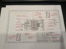
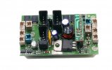
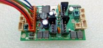
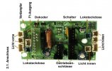
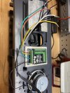
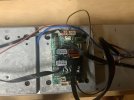
I run a 10 amp NCE DCC Powerpro System. The A unit has what I think is a standard factory installed Massoth decoder. I have hunted around for info on upgrading, but found nothing. I do have the PCB pin out. See below for pic of board in my F7 and the pin out. The loco has the LGB Direct decoder logo on the bottom (#3 in pic below).

I am thinking an upgrade will require me ripping out the Massoth board and retiring to the Loksound, but not sure.

So two questions: Can I upgrade to the Loksound? How? Thanks in advance.C919B16A-2D43-4EDB-BB6B-3CF54C0C0E6F.jpeg1F4FE96D-2E99-48FF-870D-8C282865DC65.jpeg35544C98-84B9-4071-A6E1-F93F89199CFB.jpeg
 
You can always upgrade, but there will be a little work, as none of the original connectors will mate with your new decoder.

You have two options:
Cut off every connector, and wire into your Loksound, or make/use an adapter board.

Personally, I would mount the decoder.
Swap the leads from the motor-blocks wire individual sockets/wires. - Test track and motor is OK.
Next work-through the lighting. - Test.
Then sound..

PhilP
 
You should also check what voltage lights you have on your loco and adjust the lighting outputs on your decoder to match before testing the lights. I’m sure many of us would admit to forgetting to do this and then having to replace blown bulbs!
 
You should also check what voltage lights you have on your loco and adjust the lighting outputs on your decoder to match before testing the lights. I’m sure many of us would admit to forgetting to do this and then having to replace blown bulbs!
Certainly Massoth warn about the lighting circuits having full voltage, not sure if Loksound do as well. For my money I would be tempted to update the lighting CV’s to be as low as you can but so that you can see some light. You can then up the CV to a visible sight, IMHO most lights tend to be too bright on our locs anyway so subtle just so that visible in daylight is good.
 
MTS-Line make a LGB loco adapter which has a 10 pin LGB DCC interface on it and also includes a 5V regulator for lights. It has all the LGB motor-block and lighting connectors on it so it makes it easy to connect any DCC decoder to the existing loco wiring.

MTS 84101000 DCC Schnittstellenplatine Spur-G Ersatzteil LGB


Analog configuration with LGB 10 Pin interface bypass plug installed...

mts-line LGB analog-DCC interface.jpg

With LGB 10 Pin DCC interface cable connected.

MTS 84101000 2.jpg

This is a slightly older version of the board but the interface connection for the loco wiring are the same.

mts-line LGB analog-DCC interface 2.jpg
 
Last edited:
ML Train de (Modell Land) make a LGB loco adapter which has a 10 pin LGV DCC interface on it and also includes a 5V regulator for lights. It has all the LGB motor-block and lighting connectors on it so it makes it easy to connect any DCC decode to the existing loco wiring.

I don't have the details handy now, but will post them later today.
Thanks for the help, look forward to more details.
 
On the lights, I think as long as I have the shell open I will swap them all out for LEDs.
On larger LGB locomotives such as your F7A units there's space for using the DCC Interface Board mentioned previously. But on smaller locomotives such as a Forney steamer, there's only space for a DCC decoder, not two boards. And for the ESU sound decoders, you need to use an ESU LokProgrammer for downloading sound files from the ESU library and setting up the Lights and AUX Terminals for voltage output, incandescent v. LED lights, motor type, etc. The ESU USA wholesale distributor has been out of stock on the LokProgrammer and the LokSound 5XL since late last year due to supply chain production problems in Germany. I did find some from an ESU dealer in Germany so I have the LokProgrammer available shown on my Website.

I always do fresh installs of DCC sound decoders in my customers' LGB locomotives: Always remove the old electronics and install the ESU, Massoth or Soundtraxx sound decoder. Provides for a more reliable, long term solution than using existing DCC Interfaces on old LGB circuit boards that could fail down the pike. But some DIY hobbyists find it easier to just use the DCC Interface on old LGB factory circuit boards for their conversion projects.
 
The original post does show a LGB 2 motor DCC non sound decoder (red socket is SUSI for adding a sound SUSI sound unit). The F7B has the sound with cables going to the A unit (2 wire for track power, 4 wire for speaker). Original post does state user wants to keep all the same manufacturer for all dcc engines.
The last postings I saw show an older LGB dc board which requires the 55027 DCC board but still no sound!! Also the LGB decoders do not have a 5 volt only light control, there are CV's to adjust light output voltages for low voltage like 5 volts and up to full track power minus the bridge power drop. Note LGB runs smoke at 6 volts but calls them 5 volt units.

SO, lets get back to the first post wants all the same DCC mfg boards in all the engines.
 
On larger LGB locomotives such as your F7A units there's space for using the DCC Interface Board mentioned previously. But on smaller locomotives such as a Forney steamer, there's only space for a DCC decoder, not two boards. And for the ESU sound decoders, you need to use an ESU LokProgrammer for downloading sound files from the ESU library and setting up the Lights and AUX Terminals for voltage output, incandescent v. LED lights, motor type, etc. The ESU USA wholesale distributor has been out of stock on the LokProgrammer and the LokSound 5XL since late last year due to supply chain production problems in Germany. I did find some from an ESU dealer in Germany so I have the LokProgrammer available shown on my Website.

I always do fresh installs of DCC sound decoders in my customers' LGB locomotives: Always remove the old electronics and install the ESU, Massoth or Soundtraxx sound decoder. Provides for a more reliable, long term solution than using existing DCC Interfaces on old LGB circuit boards that could fail down the pike. But some DIY hobbyists find it easier to just use the DCC Interface on old LGB factory circuit boards for their conversion projects.
That is my plan yes. Happily I have a Loksound programmer and a decoder already.
 
Back again, working to install the Loksound 5XL into the LGB F7 A and B unit. LGB #21576. Based on forum advice, I am taking it slow, starting with the track and motor connections.

It’s a two motor loco. I was able to figure out which were the track and motor wires on the existing Massoth decoder. I wired them into the 5XL (two wires each into the track +/right and -/left and motor +/right and -/left screw terminals.

Good news: the decoder came up as expected both on my NCE Powerpro cab and the Loksound programmer. Using the programmer, I was able to address it and see the sound files I had preloaded and all the factory pre-settings.

Bad news: the motors aren’t responding at all when I accelerate using the cab.

I’ve debugged a little. As expected, I am measuring 22 volts DCC between the left and right track screw terminals on the 5XL when the loco is on the powered main. But I measure no voltage between the motor left and right screw terminals when I have the cab tell the loco to run at full power. I checked to make sure I have the right motor wires, and the work - the motors run when I apply DC voltage to them outside the 5XL.

So I must be missing something. I’ve done no decoder programming other than the long address. The factory Massoth decoder is still in place, all the light, speaker and reed switch wires are still wired into it.

Any ideas?

I run a 10 amp NCE DCC Powerpro System.
 
Have you tried the default short address of '3'?

Are you sure you have set the long address correctly?

Can your system cope with the value of long address you have chosen?

Does your system alter CV29 for you? - This needs changing to use a long address.

Post values of the following CV's :
CV1 short address
CV17
CV18
CV29
And we can have a look.

PhilP
 
When I fitted the same decoder (ESU Locosound5XL) to the exact same locomotive (LGB F7A and B) I had the same problem that when I opened the throttle nothing happened, the motors didn't turn. I imediately thought that I had made a mistake with the wiring or the decoder was faulty. A quick phone call to the supplier of the decoder and the issue was resolved. With that sound file, when you turn up the throttle, the prime mover changes from idling sound slowly building to higher revs with associated electrical noise. Then after a few seconds, the decoder sends power to the motors and the loco starts to move. It is a great effect of realism. On my loco, I have set the acceleration to a high value and it takes around 30 seconds to acheive max speed, it is a great decoder.
Are you falling for the same thing?
Alan
Might be i will check
 
Back again, working to install the Loksound 5XL into the LGB F7 A and B unit. LGB #21576. Based on forum advice, I am taking it slow, starting with the track and motor connections.

It’s a two motor loco. I was able to figure out which were the track and motor wires on the existing Massoth decoder. I wired them into the 5XL (two wires each into the track +/right and -/left and motor +/right and -/left screw terminals.

Good news: the decoder came up as expected both on my NCE Powerpro cab and the Loksound programmer. Using the programmer, I was able to address it and see the sound files I had preloaded and all the factory pre-settings.

Bad news: the motors aren’t responding at all when I accelerate using the cab.

I’ve debugged a little. As expected, I am measuring 22 volts DCC between the left and right track screw terminals on the 5XL when the loco is on the powered main. But I measure no voltage between the motor left and right screw terminals when I have the cab tell the loco to run at full power. I checked to make sure I have the right motor wires, and the work - the motors run when I apply DC voltage to them outside the 5XL.

So I must be missing something. I’ve done no decoder programming other than the long address. The factory Massoth decoder is still in place, all the light, speaker and reed switch wires are still wired into it.

Any ideas?

I run a 10 amp NCE DCC Powerpro System.
When I've converted the LGB 4 pin connector plug to 5 XL decoders I snip the ends and then test using an old analogue DC controller and label the track inputs and the motor inputs. Apply voltage to the track and using a multimeter measure until you find the left/right track leads. Label these, then other 2 are your +/- motor. Input all 4 connections to the 5 XL and test motor direction. If moving in reverse switch the +/- leads. This is where the old color coding of the LGB wires really helped, the newer ones dont have it. Do the same for the second motor block. One you have determined polarity on the motor then connect your leads. I combine them and then run the LGB color-coded wires into the 5 XL so I know exactly what is what by looking at it.

BE7EB412-0A52-42DD-9B92-D95B7426A716.jpeg
 
Last edited:
When I've converted the LGB 4 pin connector plug to 5 XL decoders I snip the ends and then test using an old analogue DC controller and label the track inputs and the motor inputs. Apply voltage to the track and using a multimeter measure until you find the left/right track leads. Label these, then other 2 are your +/- motor. Input all 4 connections to the 5 XL and test motor direction. If moving in reverse switch the +/- leads. This is where the old color coding of the LGB wires really helped, the newer ones dont have it. Do the same for the second motor block. One you have determined polarity on the motor then connect your leads. I combine them and then run the LGB color-coded wires into the 5 XL so I know exactly what is what by looking at it.

View attachment 304928
Thanks, I have black wires but have figured out which is which, pretty much as you describe. The issue is no voltage to the motors when I apply throttle.
 
Have you tried the default short address of '3'?

Are you sure you have set the long address correctly?

Can your system cope with the value of long address you have chosen?

Does your system alter CV29 for you? - This needs changing to use a long address.

Post values of the following CV's :
CV1 short address
CV17
CV18
CV29
And we can have a look.

PhilP
I don't think the address is the issue. The procab reads it and when I put it in programming mode verifies that it is an ESU (by manufacturer number) and gives me the software version. Same on the Loksound programmer, it shows me everything. The issue is no voltage going out the motor wires when I accelerate the throttle.
 
The factory Massoth decoder is still in place, all the light, speaker and reed switch wires are still wired into it.
You did make the track and motor connections directly from the motor blocks and disconnected the two motor block connectors from the factory On-board decoder, correct? I'd label all the connectors then completely remove the original On-Board decoder before trying anything else with the ESU decoder.

Also suggest you remove the ESU 5XL, hook up a known functioning DC motor to it and check that the 5XL is working using your Lokprogrammer. If you've got a small 4 or 8 ohm speaker you can verify the decoder sound output is working at the same time.
 
Last edited:
You did make the track and motor connections directly from the motor blocks and disconnected the two motor block connectors from the factory On-board decoder, correct? I'd label all the connectors then completely remove the original On-Board decoder before trying anything else with the ESU decoder.

Also suggest you remove the ESU 5XL, hook up a known functioning DC motor to it and check that the 5XL is working using your Lokprogrammer. If you've got a small 4 or 8 ohm speaker you can verify the decoder sound output is working at the same time.
Yes track and mortar wires clipped from the Massoth connectors. I’ve got the right ones and they are labeled. I’m going to try a new decoder.
 
Back
Top