Which wire is which?

SevenOfDiamonds

Registered
Country flag
Good day all

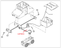
I've picked up an incomplete LGB 22300 steeple cab loco. The missing bit (which I already have in stock) is a standard 4-wheel 4-pin motor block. Unfortunately, whoever separated the motor block from the rest didn't unplug the only cable joining the two parts . . .
1675520137229.png

. . . they simply cut the cable! So, I need to join that four-strand cable (black-black-brown-black) to a new plug (or maybe four crimp connectors) but which wire goes to which pin on the motor block? All of the other electrical stuff is present and correct (and, unnecessarily, uses the standard white/green/yellow/brown wires).

I hope someone can help.

Regards

David
 
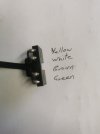
Does this help?
16755234901451695955002498904917.jpg
Literally, as it goes across your cable..

It doesn't matter if you get the whole lot the wrong way round, as you will be swapping both track and motor polarity. :nerd:

PhilP
 
Good day all

I've picked up an incomplete LGB 22300 steeple cab loco. The missing bit (which I already have in stock) is a standard 4-wheel 4-pin motor block. Unfortunately, whoever separated the motor block from the rest didn't unplug the only cable joining the two parts . . .

View attachment 309701

. . . they simply cut the cable! So, I need to join that four-strand cable (black-black-brown-black) to a new plug (or maybe four crimp connectors) but which wire goes to which pin on the motor block? All of the other electrical stuff is present and correct (and, unnecessarily, uses the standard white/green/yellow/brown wires).

I hope someone can help.

Regards

David
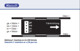
David - Below is the standard wiring convention for most LGB motor blocks, but you should always double check by testing the wires using low voltage on a DC tranformer to confirm. On LGB motor blocks the German abbreviation for the color-coded wires are marked. Normally the two outside wires are motor (+yellow; - green) and two inside wires are track power (+white; -brown). But there are some exceptions.
LGB MOTOR BLOCK STANDARD CONFIGURATION.png
 
The problem is that if the wires are non standard colours, it might be wired standard at the other end
 
The problem is that if the wires are non standard colours, it might be wired standard at the other end
Not sure what you're saying. Many of the LGB locomotives use non-colored code "black" wires set but the motor blocks are marked with German abbreviations for the standard wire colors used for wiring. The vast majority of Pre-Marklin (2006) LGB motor blocks and electronics are wired as the Massoth diagram indicates with the two outer motor block pins for the motor, and the two inner pins for the track power. As has already been stated, the 4-lead cable can be soldered to the connector either way except the polarity will be reversed. Solder the four wires of the two 4-lead cables together by first inserting shrink wrap over each wire, and then test the the locomotive. If it moves forward using the forward dial on the controller, Eureka!, then move the shrink wrap over the solder joints and heat it, and you're done. If the locomotive moves in reverse with the forward dial on the controller, unsolder the joints and reverse the cable and resolder, etc. A lot of this stuff is trial and error, without destroying something obviously in the process!
 
OK looks like I was mistaken. Working with mains voltage all day makes you doubly careful of where you put wires!
 
The key is not to mix the motor and pickup wires, as Phil says if you swop them round iwithin their types it matters little. To check it out I always use a meter on the wires for continuity off the track, thus any 2 that give you a resistance reading will be the motor wires.

DISCLAIMER
That does not work on a 3 pin motor as one of the motor leads is commonly wired to one of the pickup wires on a 3 pin chassis I.
 
Thanks for all your responses. I was already aware of the green-brown-white-yellow (gn-bn-ws-ge) sequencing of the pins on the motor block. I just hadn't thought it through far enough to realise that the 4-lead cable would be in the same order (or reversed, of course). Whereas other cables (that plug into the 4 pins on the motor block) that I've seen are all black, the one on my recently acquired model is black-brown-black-black, so I just connected brown to brown, and the others in sequence . . . and it works (analogue, as designed by LGB in this 2000-2003 model)!

Now, I wonder how I'd go about interposing a digital decoder.

Thanks again to one and all. I find that, in writing down a request for help, even before hitting "Post Reply", the 'little grey cells' often spring into action. In this case, it was someone else's 'little grey cells' that solved the problem.

Regards

David
 
Regarding your statement: "Now, I wonder how I'd go about interposing a digital decoder." There's lots of postings available on this site with advice on converting locomotives from DC analog to DCC digital operation. You'll need a DCC system to operate any DCC-equipped locomotives, of course. To convert an LGB locomotive to DCC, you can use the DCC Interface on the factory-installed circuit board, if it has one, or, even if it does have the Interface connector, you can do a "clean install" like I do and remove the factory circuit board and replace it with a DCC decoder, sound or non-sound. Check out the postings that already exist on this topic.
 
The tiny engine block wheels (read Chloe, Olmana, etc.) have the motor/track contacts reversed, that is outer posts are track and inner are motor.
 
Back
Top