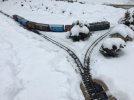
Wiring plan for my WYE section.

Ollyman66

Registered
Country flag
Hello everyone,

I received some great advice from Phil and Graham on my last post from the 22nd of November 2021.
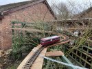
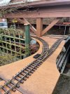
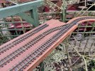
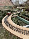
Since then l have bought a Massoth 8157001 module and completed my reverse loop and Wye section of track.

I’m now at the wiring stage and
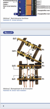
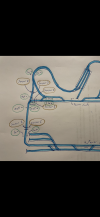
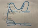
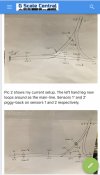
would like to know exactly which wires go to where on the Wye section drawn in diagram No2.
Not sure how to piggy pack the wiring for two insulated sections 1 and 2

I find all this wiring rather confusing.

Hope someone can help

Thanks, Oliver.154BE47B-5FB5-4688-A30C-3B2364684C9B.jpegAF832879-4FAB-4387-821B-D55BAF858EC3.pngD7A6F85D-2B02-4203-8C43-6BBAB0E1E5A6.jpeg3DB373DF-78AC-4ED3-AB21-F8F4A710E835.jpegDBB9AB4F-3AAD-43C4-A217-D931ED846958.jpeg
9C04F3FD-F3E6-40BC-BCA2-01B4A6D05489.png
 

Attachments

  • E3CEF888-0759-4ACC-8097-B8906B36663D.jpeg
    E3CEF888-0759-4ACC-8097-B8906B36663D.jpeg
    509.8 KB · Views: 0
The Sensor 1 and Sensor 1' in the second diagram are wired in parallel to the "Sensor 1" connection on the 8157001. Likewise the Sensor 2 and Sensor 2' are wired in parallel to the "Sensor 2" connection on the 8157001.

Some things to keep in mind for the 8157001:
1. You must decide which rails on both the main part of your layout and the reversing segment are going to be "+" and "-". It does not matter which rails are labelled "+" or "-" as long as you are consistent.
2. The "In" +/- are track power into the 8157001 from the main part of your layout. Only one pair of the two sets of connectors need to be used.
3. The "Out" +/- are power out from the 8157001 to the reversing segment.

Now, most importantly
4. Sensor 1 always goes between a Main(In) + rail and reversing segment (Out) + rail.
5. Sensor 2 always goes between a Main(In) - rail and the reversing segment(Out) - rail
6. Sensor 3 always goes between a Main(In) - rail and the reversing segment(Out) + rail
7. Sensor 4 always goes between a Main(In) + rail and the reversing segment(Out) - rail.

Because your yard rails only connect to the loop rails through the reversing segment they can end up powered by your booster either of two ways relative to the reversing segment. Whether you need a Sensor 1' and Sensor 2' pair or a Sensor 3' and Sensor 4' pair is determined by 4 through 7 above.

One other note: I do recommend you use the diodes on the sensor track connections as shown in Illustration 3 of the 8157001 manual. I used a terminal block intermediate between the wires from the sensors and the sensor input to the reversing module. That made it easy to parallel the sensor connections. It also meant only a single wire with diode was connected for each sensor input of module and terminal block.

Hope this helps.
 
Hello Phil,

Thanks very much for all this information which is most helpful.
I have drawn a rough diagram of my revised layout with sensor positions.
Eventually l will draw a wiring diagram which will make it easier for me to understand.
Where would you mount the reverse loop module?

Oliver.


FC52E570-CFFB-463A-9785-6D3BF1F443DA.pngA4EEF4E9-D2AA-4796-8362-2CF2E7079C09.jpeg
 
Where would you mount the reverse loop module?
I'd put the module in a Pola type building somewhere convenient on the layout that minimizes wire lengths. You can co-locate a 4 ch switch decoder or two in same building to save on decoder costs if your turnouts are (or will be) DCC controlled. Perhaps a Crossing Keepers hut located in the triangle of the wye or a freight shed near the entrance to the yard. The building will provide more than adequate protection from the weather for the modules.

but it really makes things complex.
Not really that much more complex than having multiple boosters and making sure booster zones are "in phase" at the transitions. But, it can be confusing. That's why I tried to simplify understanding with the "sensor rules" 4 through 7 in post 2. I admit it took me a good hour or two initially figuring out how to connect the third sensor pair for my configuration. This configuration is not shown in the manual. My setup worked correctly from the start so I must have done something right! The sensor rules can be applied to the situation where two reverse loops are connected by a single track with four sensor pairs, two for each loop. A single reverse loop module reverses the polarity of the connecting track.
 
DCC autoreversers don't need extra boosters.

You take his plan, and only have the insulated joints to stop a short. You get ONE autoreverser, connect 2 leads to the layout, the other 2 leads to the insulated section.. DONE...

Not complex at all, way less work and less confusing than this setup. Like I said, I am glad I do not subscribe to the doctrine that short-triggered autoreversers are bad. (neither does the majority of the United States).

No sensors, only enough insulators to stop the short from the "reversing loop", and 4 wires, 2 to the source and 2 to the insulated section.

Way less complex.

(Not trying to start argument, I DO realize the choice was made to use a sensor-based autoreverser, but your comparision is misleading/untrue)

Greg
 
Last edited:
DCC autoreversers don't need extra boosters.
I never said they do. The ONE Massoth reverse module Oliver needs is DCC and does not need an extra booster either. That wasn't my point. Anybody that has more than one power zone needs to keep track of the rail "polarity" so shorts don't happen when a train crosses zones. The zones need to be in phase. This is true whether the power zones are fed by multiple boosters or a single booster. Keeping track of the "polarity" of the Massoth Reverse loop module IN and Out feeds during initial setup is not that different.

Not trying to start argument
Yes, you are!:devil:
 
Last edited:
OK, I read your post, and you are right, you compared multiple boosters and an autoreversing section with what? Your comparison was flawed.

The point is a "short detection" type of autoreverser in the layout above would definitely be WAY less complex than what you have. You have SIX sensor sections, and the effort to get them right has taken quite a lot of explaining and drawings.

With the other type, again just the insulators and 4 wires connected to a single box. Period.

What would happen with 3 booster districts? Someone might be in an insane asylum.

You did a great job making it work right (on paper), but a novice could have done the "shorting detection type" himself.

Greg
 
I think a lot of the problem (with aversion to 'short-detection') is the terminology?

We are taught that a 'short circuit' (and sparks :devil:) are bad..
So the mention of same, and our attention to the units operation, means that we are looking at the break in the track.
This means we see any arcing (at this point) which must be bad, mustn't it? :wondering:

We are taught that arcing / sparking is bad. It will 'burn-away' our wheels, causing pitting. The arcing will cause damage to our delicate (expensive?) electronic equipment..

"short circuits are bad!" is the mantra..

If the terminology were different, none of us would bat an eyelid, and would use this method, as the wiring is so much simpler.

If it was called "bridge detection" (say) and had been from the start, then I think it would be the norm, everywhere?

If the instructions were:

"Bridge detection, senses when a wheel 'bridges' the insulated joiner, between sections....."

No mention of "short" anywhere.. :)
Simples! :nod::nod::nod:

PhilP
 
OK, I read your post, and you are right, you compared multiple boosters and an autoreversing section with what?
The need to know what rails are connected to which of the two power leads! That was my whole and only point If perhaps not made very clearly. I am not advocating for one style of auto reverser over another. I happened to choose the Massoth, actually the LGB iteration of the Massoth, over a PSX-AR because it is weather resistant out of the box and does not need the customized protection a bare circuit board requires (speaking of "way more work").

By the way, my reverse loop module has worked just fine in the garden in all kinds of weather more than four years now - not just "on paper"! But turnouts - they don't like ice and snow so much!

Wye - 1.jpeg

I'm going to hold out an olive branch now, no pun intended, so Oliver can have his thread back.
 
Last edited:
Now, most importantly
4. Sensor 1 always goes between a Main(In) + rail and reversing segment (Out) + rail.
5. Sensor 2 always goes between a Main(In) - rail and the reversing segment(Out) - rail
6. Sensor 3 always goes between a Main(In) - rail and the reversing segment(Out) + rail
7. Sensor 4 always goes between a Main(In) + rail and the reversing segment(Out) - rail.
OK, that's really helpful. One of the questions that emerged (for me, at least) from the reverse loop gory details thread was how to wire sensors if there are more than 2 entry points. This summary says that you connect to sensors 1/2 for +-/+- joins and to sensors 3/4 for +-/-+ joins. I assume the choice of + and - for the reversing loop is arbitrary, but once you choose you need to stick with it consistently.

So, for Olly's diagram above, if he switched the polarity for his yard (lower section), he would need to replace the lower sensor connections from 2 (left rail) and 1 (right rail) with 4 (left rail joins external + with internal -) and 3 (right rail joins external - with internal +). Correct?

Loosely related question: If I had this sort of setup and wanted to add an interlock to prevent a 2nd train entering the reversing section while it was occupied, how might I do it?
 
So, for Olly's diagram above, if he switched the polarity for his yard (lower section), he would need to replace the lower sensor connections from 2 (left rail) and 1 (right rail) with 4 (left rail joins external + with internal -) and 3 (right rail joins external - with internal +). Correct?
Yes
Loosely related question: If I had this sort of setup and wanted to add an interlock to prevent a 2nd train entering the reversing section while it was occupied, how might I do it?
This question really deserves it's own thread.
 
Back
Top