Lgb 69576 motor tender to dcc???

STOP!
Before you let the magic-smoke out.. ;)

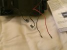
Connect the four wires from your decoder to the pins on the motor-block. - Do not connect the soundcard to anything at this point.

Make sure nothing is touching the decoder, and test the tender runs back and forth, and in the correct direction. - Hint: If both your loco and the decoder in the tender have the same address: You can put them on the track a short distance apart. They should run in the same direction, and at approximately the same speed.

If all is well, you can connect the two motor/track wires from the soundcard to pick up power.

You may want to wait for someone else to chip in about this. I have an eye problem at the moment, and going through the documentation is presently a problem for me.

PhilP.
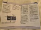
I did hook up the decoder wires to the four pins and tried programming it. That worked but the tender doesn’t move
 
I did hook up the decoder wires to the four pins and tried programming it. That worked but the tender doesn’t move
Double-check you have the four wires in the right order, then:

If connected, disconnect the soundcard.

With just the tender, can you read CV's '1' and '29'.
Make a note of the values.

Do the same with your loco.

If necessary, change the values of the CV's in the tender, to match those in the loco.

Test both loco and tender (separately) to see if they work.

PhilP.
 
Ok sounds like you may be a little out of your depth here, no insult in that we all have to start somewhere and DCC plus fitting can be a steep learning curve.

Ok so you have a sound board, is this is not a DCC one? To get this working you would need to connect it to the motor power.

A complete rewire of the connections from wheel pickups to motor on the chassis is required, you could use the 4 pin plug but would need to cut the wires to your sound board. Before that cut you need to understand what wire is what. The Terminal block will be your friend as previously mentioned. Post 14 shows you have the right idea.

Do you have an electric Multimeter to test the electrics? You can use this to test what wires do what, remove the plug and test each of the pins in the chassis. 2 will connect to the wheels 1 each side when the pin and wheel is touched, the other 2 will connect to the motor and give in effect a positive reading via the 2 pins. The pins should be the same for each 4 pin plug but I always test to be sure.

If you do not fancy cutting the plug wire, LGB prongs and new wire will connect to the 4 pins in the chassis, I tend to colour code these to LGB standards. Pic below shows code as used.

Post 12 is pretty much what you need to do duplicated in part in pic below, if you use a terminal block as suggested you should get things correct.

Not sure if you would be keeping loco lights, if so these would be powered from a decoder in here.

The pic in post 12 can be a bit confusing, the 6 wires at the top go to an interface that is only oresent in certain board instances. The motor and pickup colours are duplicated with the BN brown and BL blue are light wires.

I think enough for now, see how you get on and more help available if required.
I believe the sound board is dc.
 
Double-check you have the four wires in the right order, then:

If connected, disconnect the soundcard.

With just the tender, can you read CV's '1' and '29'.
Make a note of the values.

Do the same with your loco.

If necessary, change the values of the CV's in the tender, to match those in the loco.

Test both loco and tender (separately) to see if they work.

PhilP.
The sound board is disconnected. It was hooked up by the factory four pin connector. I’ll make sure it isn’t touching anything because as of now it’s resting on the sound board. Then I’ll do the cv thing and report back. The lgb motor block is labeled. I went green to green, white to white, yellow to yellow, brown to brown. Could it be labeled wrong?
 
The lgb motor block is labeled. I went green to green, white to white, yellow to yellow, brown to brown. Could it be labeled wrong?
I would very much doubt it is incorrectly wired.

The default address of a 'new' decoder is '3'.

If your loco, or the decoder you are fitting have come from someone else, the addresses may have been changed.

PhilP.
 
I would very much doubt it is incorrectly wired.

The default address of a 'new' decoder is '3'.

If your loco, or the decoder you are fitting have come from someone else, the addresses may have been changed.

PhilP.
Brand new from massoth. The decoder fitting in the loco is working fine maybe matching the cvs will do it. But as of now it’s not moving forward or reverse. But does make the sounds when programmed
 
If as Phil says you do not at this stage try to electrically connect the 2 parts then both should be moving if all is fitted correct so reading your notes am I right in saying that you have fitted deciders in both parts?

The loco is running ok?

The tender is not?

Oh not sure if you have worked this out, if you click on a picture to get a full screen you can scroll through them all using the > and < arrows in the middle if the page.
Thanks. I didn’t know about scrolling through pictures. I disconnected the sound card completely. I reprogram to make sure i had the right loco address. I double checked the wire leads and they are correct.
1. Yes the loco works

2. NOW the tender also works!!!!

I will check the cv’s of both the loco and tender as advised.
 
I would very much doubt it is incorrectly wired.

The default address of a 'new' decoder is '3'.

If your loco, or the decoder you are fitting have come from someone else, the addresses may have been changed.

PhilP.
The tender does work with the four wires connected straight to the motor pins. Just starts off at a higher speed step. Starts moving around 5 or 6
 
Can i retain the rear light by connecting the red and black leads coming from the light straight to the pins labeled
-LI-R: light rear (-)
And
-Dek+: common terminal (+)
 

Attachments

  • image.jpg
    image.jpg
    789.3 KB · Views: 0
  • image.jpg
    image.jpg
    701.4 KB · Views: 0
Is there anyway to retain the factory sound card that came with the tender?

Or should i just get one made by massoth so basically the tender would be dcc and controlled through the cab?
 
Last edited:
Ok 2 ways to do this, a larger decoder in the loco with track power and motor power linked between the loco and tender thus 4 wires joining the two. The other way with 2 smaller decoders one in loco the other in tender again 4 wires joining. I would be tempted to use a small 4 way screw connector block in the tender to connect the wires, this will give you the ability to check things out.

Make sure that you get the connections correct in both cases!
How would i connect the 4 way screw terminals? Do they sell the crimped ends that slide on the motor pins separately? If so i could use those with some wire to run to the junction box? Correct?


I think I’m over thinking. I can just cut the wires going to the motor pins now and put in the terminal box!!!!!
Any recommendations?
 
So many questions! Easy Tiger, let's deal with one thing at a time. :nod:

So, we have both loco and tender running..

1. Do they run in the same direction?

2. Do they both respond to the same address. - Both move when the same address is selected on your Cab?

3. What is the value of CV 29:
For the loco?
For the tender?

Amongst other things, CV 29 sets the number of speed-step, and whether a 'standard' or 'custom' speed-curve is used. - If these do not match, the two units will not start and run at similar speeds.

Rear Light:
Yes, you can use the LR and Dec + connections, but there will be a CV to set a divider. You use this to match the lighting voltage to the rating of the bulb.
If your rear-light is a plug-in bulb, does it have a flat end? - If so, it is most likely a 5V bulb, set the divider to '6'.
This light will only be energised (on) when the tender is running in reverse.

We can get the speeds right, and the rear light working first, then start looking at the sound..

PhilP.
 
Back
Top