As stated before, the rolling tests shown the detrimental effects of free plays in the 2 bogies assembly.
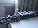
Accordingly special care was put in the fulcrum design and ball bearings are widely used.
The screws connecting each bogie to the common chassis are installed with a ball bearing at the chassis level.
Then for the fulcrum a large cylinder is created to counter act the base plate rocking sidewise.

This large cylinder is fitted with 2 ball bearings around the fulcrum screw and is installed on the common chassis (one ball bearing at the top, one ball bearing at the bottom).

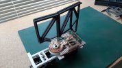
The base plate has been machined ( see video of the previous post ) as per the following 3D design.


When assembled with the cylinder we get this :


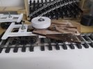
Now we have to create the 8 ribs ( twice four for each chassis ) which will be fixed onto the base plate.
Joël started to machine the ribs with the same material as the one used for the base plate ( plexiglas) but it appeared this is more difficult and also very long lasting. (several hours of machining per rib). So we looked for different material.
At the end, Joël decided to evaluate if these parts might be done with 3D printing.
So he created a new 3D file and started the printing.
The result is quite promising and the assembly of the 4 ribs onto the base plate much easier than with the previous design and parts acquisition.
However for the complete wagon 24 printing hours are required for the 8 ribs !!

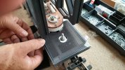
When assembled

The following picture shows the slot which allows this rib to be connected to the base plate side

Like that:


Then an inner rib will close this complete rib assembly.
This is where we are today.
The next major assembly of the wagon will be the cradle placed in between the 2 half wagons and carrying the transformer. The design is currently underway. It will be made of 3D printed parts as well, but being quite long, reinforced with 2 aluminium U shaped rails.
Later on we intend to put details features (cabinet, hand rail, pumps,... etc) on this skeleton to make it more real.


")
.jpg")
.jpg")
.jpg")
.jpg")
.jpg")
.jpg")
.jpg")


.jpg")
.jpg")
.jpg")


") we are adding manual brakes
we are adding manual brakes.jpg")
.jpg")


