Battery conversion Bachman railtruck/Goose I

maxi-model

UK/US/ROW steam narrow gauge railways 1:1
Country flag
Here, I hope, should be a fairly simple conversion. My plan is to remove the track pick ups but I would like to retain the circuit board so I do not have to mess around with the wiring that is there for the motors and LED's. Yes, I have had a look at George Scheyers pages, where there is a conversion of this product shown but I don't want to go down his suggested "ditch the board" route.

My question is where do I solder in the outputs from the ESC to power the thing and could I make use of any the 4 terminals rather than soldering into a point on the board ? I have included the schematic for DC operation and the table for connections for both DC & DCC connections. I have not shown the DCC schematic that Bachmann supply.
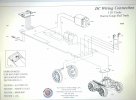
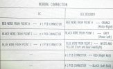
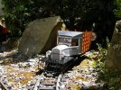
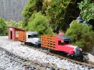
20201121_190835.jpg20201121_191138.jpg

Just so you know the Battery/TX/RX/ESC/Sound unit is a fully wired up and ready to go Foswowks package with the "correct" MLS petrol railcar sound card. This will be enclosed on the load deck with a scratch built "garden shed" of the appearance of the one constructed for Goose I in the latter days of its operation. Its will have opening doors at the rear, as per the prototype. Answers made in layman's terms please, prefferably of one sylable if possible would be appreciated. I.E. Which wire goes where and "don't do that, all you will get is magic white smoke". Thanking you all in anticipation. Max
 
If you disconnect the track pickups, and wire into those connections to the board, then the Goose will behave just as if it were powered from analogue track voltage, with the added bonus of the sounds running all the time.

Lights will go off, when the Goose comes to a standstill, though.

PhilP.
 
There is common wisdom over here, NEVER trust the schematic for Bachmann or Aristo products, always verify with a meter.

My best advice is to figure it out if you want to use the existing board. You have commented before that electronics is not your strong suit, so if using an ohmmeter to verify connections is not comfortable, then I recommend disconnecting the lights and motor from the board and wire to them directly.

Greg
 
Hello Max,
Before committing to ownership/running of the little rail-truck I would investigate where you can buy spares for the drive mechanism.
They mostly fail sooner rather than later and Bachmann do not have spares.
 
You didn't miss anything Greg.
Maybe not too late for Max to bail.
Because break it will and no spares........

Maybe what this forum needs is a list of bad models and what is wrong with them!!!

AND/OR, list the really good ones.

AND/OR, list models that can be improved from stock to make them excellent.
 
Last edited:
I have Couple of these and I wonder if radio control car parts would be useful to fix them when they break, which they will. Rc car stuff has some real neat trans axle type gearboxes all kind of ratios
 
These things always had a bad wrap about them, so I read up about all the problems before sending money.
Bloke called George Schrier (sp.) ? wrote them up, and I was them aware of what to expect.
Main fault was gears stripping, and driveshaft breaking after jamming up while running.
First rule, if it don't move when power is applied, do NOT push it... that is just asking to break the drive shaft which is 'scale size, in plastic.
The issue of gears getting out of mesh and stripping, is caused by faulty assembly, but, there is a fix. The cover plate, that holds the gears etc. in place, has screws that go into a blind hole, and the screws on faulty models are too long, hence the cover don't do its job proper like. There is a solution. The screws that hold the cowcatcher on, are the correct size. I modified mine accordingly after its first run, and heard the ominous rattle from the gearbox. Been running sweet as now for 8 years. Remember, no pushing !


DSCF2607.JPG

Christmas Day 2013, it didn't come in a Red box, but rather, a bloke in a funny red suit.

DSCF2822.JPG

These Geese were/are plentiful in our environment, so I organised a Goose Shoot at Taita Gorge one day. We bagged 3 (and one got 'left at home' by mistake). We all followed the aforementioned advice, and all are running today, one was even at Rail-Ex last week.
 
Last edited:
I think that I am right in saying that the single wheel is the power wheel for these right? If so and if they have poorly designed beaking gear sets why not replace with a single axle power motor. Fosworks do these with varying options of customer wheels as well. You need to look a long way down in their on line listing to find them starting with MOT-100.
 
Well. I wasn't expecting all that doom and gloom. I have owned my "Rail Truck" since I bought it new some 14 years ago from dear old Garden Railway Specialists ( I was a bit naive in those days and probably still am ) so a bit late to bail out :D . When I saw the those close out prices a little while back I did think, "Do I need a spare and an heir ?" Mine does not get that much running, like most of my stock. The Fosworks TX, that will control its new "heart" incorporates an inertia control that should help minimize strain on the drive train. True, I will be adding some significant weight that will place some more strain on that proven weak link. It helps that my line is pretty flat. I would never ever try to push the thing along or anything else that shows a marked resistance to roll. I'm fairly well versed in model car drive trains though, having come from the 1:24/1:32 slot car world, so working out a fix should the inevitable Bachmann plastic gear fail occur might not be beyond my abilities to fix. I think I can find a source of small metal bevel or crown & pinion gear sets. But thanks for the tips.

Now, back to the plot - Phil, my original thinking was check where the wires go from the pick ups and then substitute the ESC's input for the track's. Theory - the stock circuit board carries all the necessary bits to protect the LED's from over voltage, the motor's suppressor and flipping the polarity. So long as what the ESC is feeding in is not much different from the pre-existing TE controller puts into the track (ok, I have mine set to linear and the ESC is PWM) then we should all be hunky dory. Thanks for confirming my suspicions. What could possibly go wrong ;) And if it does I'll go to plan B and gut the thing as suggested.

True Greg, most things electrical tend to mystify me. I get the bit about don't put your fingers in a mains electrical socket, or if you must wear rubber soled shoes :D At my primary school they taught us the basics, so I can just about follow a circuit diagram (as they are known here) and I might even recognize some of the symbols, like for a battery or resistor but not much else and the difference between parallel and serial wiring. I never really needed to know more, until now. While I posses a "multi-meter" I only ever use it to check voltages. So now might be the time I really need to look out a tutorial to show me how to use its other functions and capabilities. Max
 
If you disconnect the track pickups, and wire into those connections to the board, then the Goose will behave just as if it were powered from analogue track voltage, with the added bonus of the sounds running all the time.

Lights will go off, when the Goose comes to a standstill, though.

PhilP.
Phil, your post is the only one answering the question, and If I were doing the conversion, as Max is my solution also would be to use the track power connection, for all the reasons stated :)
 
So long as what the ESC is feeding in is not much different from the pre-existing TE controller puts into the track (ok, I have mine set to linear and the ESC is PWM) then we should all be hunky dory.
The obvious question having read through the content of this thread, is how does the Goose perform, if the TE is set to operate as PWM?
 
The obvious question having read through the content of this thread, is how does the Goose perform, if the TE is set to operate as PWM?
It works fine with the TE set either to PWM or Linear. I only reset my TE to Linear at some point in the past as there was advice on a forum that the Bachmann products were not overly fond of PWM and it was really the Aristo' locos that preferred their current delivered in that manner. I have no knowledge of the technical veracity surrounding this statement. The Crest TE is/was an Aristo' product in all but name. All bar 3 of my track powered vehicles are Bachmann products hence my mention of this.

My apologies to the more technically minded here if I seem to want to willfully follow the line of least resistance. I do accept your advice but here I feel the consequences of failure will not create an insurmountable "total loss" scenario. I guess I'm like most human beings.

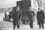
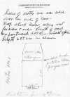
As a little aside here are a couple of pictures, one a rough drawn plan view, that I am using to construct an as near prototypical "shed" to house all the new gubbins for this rail truck. I almost overlooked the rough drawing that confirms the existence of a passenger compartment built into the Goose I's latter incarnation before scrapping. If anybody knows where I can find or access an image showing the side view, that is obstructed, of the passenger compartment access I would be most grateful. Max

Goose I modified.jpgGoose 1 plan view.jpg
 
Seems all is well with the plan of action :clap:, only quandary is your own personnel preferences for the lighting control, Fosworks have an item which may well be worth looking into.
 
Back
Top