DCC Conversion Reverse Loops

I would connect the autoreverser right at the point of the insulators, unless that is very far from a feeder, in that case run a separate feeder to the reverse loop.

Put your power to the yard at one end or the other, so that power has to flow through the minimum number of switches, and depending on the manufacturer of the switch, augment the power distribution through the switch with 14 gauge jumpers to the rails...

Greg

I'm a little confused about your recommendation for the reversing loop feeders. You are saying to draw power from the rails into the autoreveser and have it connected back to the rails, at the isolation points?
I was planning to locate the autoreverser before the feeders where I branch the signal from the CS to the circuit breakers for the 3 areas - mainline, yard, and revsersing loop. The signal from those 3 then flows out to the feeders of each isolated section, which I why i was wondering if 2 feeders for the reversing loop would be better given its 60+ feet long.
 
Last edited:
My little vid may help with regard to locations, this was a test set up of a triangle (wye) using an LGB Reverse Loop Module, but the principles are pretty much the same For a Massoth one. Note that the actual reverse section is the bit between the Isolations. What ever you create the Longest Train needs to be able to be in that section if all Metal Wheels or Unit as the system relies on a Short Circuit being created to flip the Power over on the rails. You can just make out the clicks in the unit as the loco passes into then out of the reversing section.

 
Last edited:
I would strongly recommend the DCC specialities DCC autoreverser over the Massoth/LGB for many reasons.

Won't go into them here, but I believe the question was the placement of the autoreverser.

I thought what I wrote was clear, but here goes again.

1. feed the autoreverser (output) section from the center, or you could indeed split it into 2 isolated sections with 2 feeders.
2. power the autoreverser (input) from the end of the track where you have the insulators, unless that is too far from the last feeder.

Greg

Thanks, that makes sense now. Correct I am using the DCC Specialties AR, not Massoth, though I have Massoth everything else.
 
Here's a little progress update from the past weekend. I installed the turnouts on the mainline and will be arranging the track for the inner loop and yard as the week progresses. I'm hoping to start digging to lay the gravel roadbed and wiring next weekend.

I got the 12260 double slip in place and had a short on the mainline so I put isolating clamps to the northwest side, which resolved that. I think I will still need gaps on both northeast and southwest of the double slip for the reverse loop wiring to fully isolate it from the mainline. Power in will come from the southeast reverse loop.

IMG_6002.JPG
 
Last edited:
Lots of work has gone into the expansion over the past month. Quarantine has actually allowed me to get a LOT more done than I otherwise would have.

The sub-roadbed and all the wiring are down. Starting to level out the gravel, get the track locked in, and wire up the switches and track. Next step will be to install the junction box on the side of the house and connect to the CS in the basement. My hope is to have it operational by this weekend.


IMG_6064.jpg
IMG_6065.jpg
IMG_6069.jpg
IMG_6068.jpg


Final Track Plan
BRRR_Yard_Inner_Reverse_Final.JPG
 
Last edited:
Finally got all the track down and wired up and am now in need of some assistance to debug strange behavior. I'm using LGB turnouts - 1600 on the mainline and 1200 in the yard. A short is happening on the yard breaker whenever I "close" the #2 switch. It only appears with this switch, the position of the other 6 turnouts do not seem to make a difference. If the switches are all-live I'm stumped to understand why this would be happening when closing the turnout to send the train straight (closure rail touches the 'red' rail). I tried replacing the entire switch, but the issue remains. I also tried putting isolating clamps "above" this switch, but that also has no effect.

After tracing all the wires surprisingly there appears to be continuity between the yard and mainline on the 'red' rail, which originates from 2 PSX breakers for those zones despite having isolating clamps at the two ends of the yard. The black leg does not, as expected. Red is the innermost rail in my layout for each rail pair. I have the power inputs for 2 PSX circuit breakers daisy-chained together as described to do in the manual when using multiple units and zones. I see continuity between the 2 'red' outputs from both PSX breakers when they either daisy-chained or split from a terminal block from the CS.

I'm also having some trouble with the PSX-AR on the inner reverse loop. A short is occurring over the double slip in some directions. Right now I have isolation joiners on the 2 legs to the south and on the northeast side of the double slip.

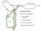
Here is the schematic I've put together showing the feeders, isolation joints, and power zones.

The mainline has 4 feeders, and the yard and inner loop both have 2 each.

Outdoor_Layout_Schematic.jpg

Any ideas or feedback would be greatly appreciated!
 
Last edited:
Finally got all the track down and wired up and am now in need of some assistance to debug strange behavior. I'm using LGB turnouts - 1600 on the mainline and 1200 in the yard. A short is happening on the yard breaker whenever I "close" the #2 switch. It only appears with this switch, the position of the other 6 turnouts do not seem to make a difference. If the switches are all-live I'm stumped to understand why this would be happening when closing the turnout to send the train straight (closure rail touches the 'red' rail). I tried replacing the entire switch, but the issue remains. I also tried putting isolating clamps "above" this switch, but that also has no effect.

After tracing all the wires surprisingly there appears to be continuity between the yard and mainline on the 'red' rail, which originates from 2 PSX breakers for those zones despite having isolating clamps at the two ends of the yard. The black leg does not, as expected. Red is the innermost rail in my layout for each rail pair. I have the power inputs for 2 PSX circuit breakers daisy-chained together as described to do in the manual when using multiple units and zones. I see continuity between the 2 'red' outputs from both PSX breakers when they either daisy-chained or split from a terminal block from the CS.

I'm also having some trouble with the PSX-AR on the inner reverse loop. A short is occurring over the double slip in some directions. Right now I have isolation joiners on the 2 legs to the south and on the northeast side of the double slip.

Here is the schematic I've put together showing the feeders, isolation joints, and power zones.

The mainline has 4 feeders, and the yard and inner loop both have 2 each.


View attachment 266219

Any ideas or feedback would be greatly appreciated!
The first thing I would do, is take out that double slip, as I reckon that is the cause of your strange problems.

A DS in a reverse loop is always going to cause issues and you have one in a triangular junction....
 
It turns out the strange switch short issue was the yard PSX settings. I had updated the trip setting to something higher than default, but must have done something inadvertent when programming it. I did a factory reset on it and that issue has gone away! A good lesson learned with DCC. I'm glad the wiring is solid, however, and it turned out to be something configurable and not electrical.

I need to spend some more time on the double slip reverse loop issue now. One of the early posts on this thread showed the all-live mapping for it.

Also, on one of the 16050 switches the throwbar plate seems tight and the EPL wont throw it. The EPL motor works fine when not connected tot hat switch and to other switches. Any ideas how i can loosen it up?
 
The first thing I would do, is take out that double slip, as I reckon that is the cause of your strange problems.

A DS in a reverse loop is always going to cause issues and you have one in a triangular junction....

Looking at the double slip power routing more closely and seeing it in action now I'm wondering if installing a second PSX-AR in the mainline loop to the northeast side would solve the issue? That would connect the 2 reverse loops back-to-back and allow me to keep the double slip. I have 2 sets of feeders in that section that I could wire back to an AR pretty easily. I dont want to lose being able to reverse in both directions.

My other thought is to isolate all 4 ends of the double slip and make it dead. The locos I run are all pretty much 2 truck, longer diesels and i think would be able to crossover as the double slip is pretty short.
 
Last edited:
My other thought is to isolate all 4 ends of the double slip and make it dead. The locos I run are all pretty much 2 truck, longer diesels and i think would be able to crossover as the double slip is pretty short.

I ended up trying this - isolation joiners on all 4 corners, and now the reverse loop works perfectly in both directions with all my locos. I did have to add the delay setting to the mainline PSX so the AR has time to do its thing without the breaker shutting down. Perhaps I'll revisit removing one of the reverse loop-side set of isolaters if I have trouble with shorter locos.

As of now everything is working as I had intended with the initial design, so thank you to everyone who had feedback and helped out!
 
Last edited:
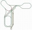
After using the double slip and inner loop as the reversing section for about a year I decided it was a lot of switching to get trains in and out and I couldnt run a figure 8 without switching. I decided to replace the double slip with a regular 22.5 degree crossover. The LGB 13200 aligns almost perfectly with the 12260. I kept the inner loop isolated below the crossover and replaced the AR with a regular PSX-1 breaker. I then moved the AR to a dedicated reversing section off an additional route I added to the mainline. This has given me a lot more running possibilities and is easier to manage. While I would love to still have the double slip on my layout it wasnt the best solution for the operating I wanted to create. Here is the updated track layout

2021_BRRR_Layout.JPG
 
Does that track plan actually work? I cannot see how. switches 9, 10, 11 combined with the loop at cherry hill and switches 14 and 15 create a loop. I would think you have to at least break the loop somewhere near switches 14 and 15, and that still does not solve the loops created by swhtichs 9 and 11.... without studying it deeply, this setup seems impossible, and also the optimal locations of the reversing sections may indeed be your 3 tracks that run parallel and at the 45 degree angle in the picture.

Are you really running this configuration? Is there a second autoreverser somewhere?

Greg

Yes it works perfectly. The switch routes to get into and out of the inner loop leads are 16/18/10 and 11. Once onto those rails then 14/15 to make the inner loop. It might be easier to see if I remove the switch numbers, which I have on there for our club operating group in case they want to use them.

9 is the switch in and out of the yard from the mainline on the north side . There is only 1 auto-reverser on the red section. There are 3 other PSX breakers - 1 on the outer mainline, 1 for the yard, and 1 for the inner section around Cherry Hill.

BRRR_2021_Layout.JPG
 
Last edited:
Well, it's a bit hard to see where your insulators are, but at first glance, it seems that there are routes you cannot travel without additional reversers.

But if you could highlight the insulators, I think I can see how it works. Wild.

Greg
The insulators are at all the points where different colors meet - both ends of the yard (yellow), and the 4 intersections of the reversing tracks (red) with the mainline (green). There is another set for the inner loop that’s just for power management of that block and isn’t really needed, which is the same concept for the yard too. It’s for a separate power block and not because of any polarity change.
The only place with a polarity change is the red reversing section.
 
I had not looked at this that closely when originally posted. I agree with Greg - Wild! The whole key making it work appears to be replacing the double-slip with a crossover. That eliminated what otherwise looks like and would have been a wye junction (and short circuit). Very creative!
 
Back
Top