Help with LGB 10345 Automatic Shuttle Missing Track Pieces

kidzntoyz

Registered
I purchased the LGB 10345 Auto Shuttle and it was supposed to be new and complete but instead is missing the isolated track sections and diodes. Since I am new and have a lot to learn regarding electricity, could I instead use the isolated track 10153 (1015U) to complete the setup for prototypical braking according to the instructions for the shuttle unit? I thought that might avoid soldering but I do know how to solder if needed. Or should I just cut the rail of a piece of short track?

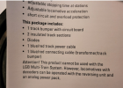
Here are the instructions: 2. Connect terminals “sw” (black) and “ws” (white) on the circuit board to the insulated track section. Loosen the screws on the insulated track sections and trap the wire between the screw and the rail. 3. Use the blue/red track power cable to connect the connectors ”bl“ (blue) and ”rt“ (red) of the terminals, respectively, to the tracks. 4. Use the blue/red connecting cable to connect the connectors ”bl“ (blue) and ”rt“ (red) on terminal “Power” of the circuit board to the DC output of an LGB throttle or power pack. 5. Plug the power supply cord into a house current outlet.

Thank you for any advice!
 
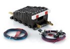
LGB 10345 Auto Shuttle and it was supposed to be new and complete but instead is missing the isolated track sections and diodes

The 10345 does not include track or diodes. The instructions are a bit arcane, but if you are using it a simple to-and-fro shuttle, you should use Mode 2 which does not require diodes. The English instructions are not very clear (being literally a direct translation for German, rather than written to make good sense in English) but if you persist with them it is possible to work it out.

IMG_2061.jpeg
 

Attachments

  • 992B4B5B-1F38-448F-B92F-8652D57708CF_1_201_a.jpeg
    992B4B5B-1F38-448F-B92F-8652D57708CF_1_201_a.jpeg
    332.4 KB · Views: 0
Beats me... it is what they currently show on-line.

This may be useful.... Retailer Instructional video which describes Mode 1 operation.
The picture on the LGB website does not show insulating track sections or diodes, but if you click on "downloads" and scroll down in the manual it does list 2 insulated track sections and diodes. The website is not clear. kidzntoyz should talk to the seller about the missing pieces. He could use two 10153s (but at about $30.00ea plus shipping?) or cut his own gaps (but fill the gaps with a small bit of plastic glued in place to keep the gap from closing). The manual shows the diodes attached with screws. Perhaps the 10153 comes with tapped holes in the rails. He could also use insulating rail clamps between sections, like those from Split Jaw ($10/pair + shipping) and put diodes under the screw heads. Someone else will have to help with the specific diodes, but they would have to handle more than about 5 amps. Best of luck with the project.

Just noticed this on eBay. LGB 1015U Insulated Track Section X2 for sale online | eBay. Looks like it's just the diodes.
 
Last edited:
but if you click on "downloads" and scroll down in the manual it does list 2 insulated track sections and diodes.

It wouldn't be the first time Marklin has changed what is shipped under a part number, but not updated the associated paperwork. ... the 10345 was introduced in 2016 so there's been plenty of time for the shipment pack to change, :eek:
 
I have three of these units and all came second hand from eBay with two pieces of 10153 insulating track each which can be fitted with a diode in the "black box" to allow the loco to be halted and then reversed at either end of the shuttle.

I have also seen laterversions of the shuttle unit where instead of two 10153 pieces of track there were just two short lengths of track (shorter than a 10153) each with one rail cut through and two holes in the rail on the cut side. A diode was wired across the gap and with the ends of it either fastened through the holes with a nut and bolt or soldered in place. Here's a link:

 
Yes you can use a 1015U to isolate the each endpoint station. I purchased a pair last year and they included the 2 insulated track sections and the diodes, and the two cables described above.

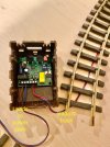
I use mode 1... and haven't tried mode 2. Here is a picture of the underside with the connections:

My picture is upside down from the diagram

Thank you for the information! I have an older set with the diodes and I don't like the abrupt stopping as the loco crosses the isolated track. I wanted to be able to setup with proportional acceleration and braking. The seller is aware and has offered to pay for any costs. Here's what I'm using them for:

1736874318728.png 1736874410765.png
 
The picture on the LGB website does not show insulating track sections or diodes, but if you click on "downloads" and scroll down in the manual it does list 2 insulated track sections and diodes. The website is not clear. kidzntoyz should talk to the seller about the missing pieces. He could use two 10153s (but at about $30.00ea plus shipping?) or cut his own gaps (but fill the gaps with a small bit of plastic glued in place to keep the gap from closing). The manual shows the diodes attached with screws. Perhaps the 10153 comes with tapped holes in the rails. He could also use insulating rail clamps between sections, like those from Split Jaw ($10/pair + shipping) and put diodes under the screw heads. Someone else will have to help with the specific diodes, but they would have to handle more than about 5 amps. Best of luck with the project.

Just noticed this on eBay. LGB 1015U Insulated Track Section X2 for sale online | eBay. Looks like it's just the diodes.
Great information, thank you! I'll order the diodes just to have them on hand. The 10153 track does come with tapped holes but I can solder instead, if I go that route. I would prefer the proportional accel and braking the unit offers. I might just look for a couple of 105mm track pieces and cut them, filling the gap with hot glue.
 
I have three of these units and all came second hand from eBay with two pieces of 10153 insulating track each which can be fitted with a diode in the "black box" to allow the loco to be halted and then reversed at either end of the shuttle.

I have also seen laterversions of the shuttle unit where instead of two 10153 pieces of track there were just two short lengths of track (shorter than a 10153) each with one rail cut through and two holes in the rail on the cut side. A diode was wired across the gap and with the ends of it either fastened through the holes with a nut and bolt or soldered in place. Here's a link:

This is very useful, thank you! I opened a unit I purchased years ago and it was also missing the track, but i didn't know better at the time and believe the seller didn't know either. Sometimes LGB pictures of products can be misleading.
 
Thank you for the information! I have an older set with the diodes and I don't like the abrupt stopping as the loco crosses the isolated track. I wanted to be able to setup with proportional acceleration and braking. The seller is aware and has offered to pay for any costs. Here's what I'm using them for:

View attachment 337501 View attachment 337502
Sounds like an honest seller. Be sure to post a video some videos of the finished project operating.
 
To slow down the acceleration and slowing of a loco, I added a 4 ohm resistor across one side of a 1 foot piece away from the diode track on each end. This also lessens the coupler slap noise. So, my track goes like this: End, diode track, 4 ohm resistor......main line........4 ohm resistor, diode, other end. Another pair of resistors can be entered also and use 3 ohm resistors for more control. (Part of my 'Kiss' changes). Keep It Simple !!
 
To slow down the acceleration and slowing of a loco, I added a 4 ohm resistor across one side of a 1 foot piece away from the diode track on each end. This also lessens the coupler slap noise. So, my track goes like this: End, diode track, 4 ohm resistor......main line........4 ohm resistor, diode, other end. Another pair of resistors can be entered also and use 3 ohm resistors for more control. (Part of my 'Kiss' changes). Keep It Simple !!
I've read about adding 1 ohm resistors to keep a logo from accelerating when going downhill so this makes good sense. What is a good way to attach a diode to the track and am I attaching it anywhere along the rail? I'm pretty decent at soldering but I've heard soldering onto brass can be difficult. My town doesn't have an electronics store anymore, such as radio shack, I suppose they're also sold online?
 
Last edited:
Split Jaw also sells a reversing unit with a cool self-adjusting feature that measures the length of track and figures out when to accelerate and decelerate for a smooth operation. It also allows in-between stops.
Very cool! I just checked out this reversing unit. I like the fact that you can do intermediate stops but you will need a magnet and read switch for each stop. Makes sense. What I don't see is controlling the acceleration and braking. I would probably have to call to get more details. Another good suggestion, thanks!
 
Yes you can use a 1015U to isolate the each endpoint station. I purchased a pair last year and they included the 2 insulated track sections and the diodes, and the two cables described above.

I use mode 1... and haven't tried mode 2. Here is a picture of the underside with the connections:

My picture is upside down from the diagram

I used the basic LGB track connectors to test out the unit in mode 2. It was a little confusing, lol, but I got it working. As your suggestion, I opened up a 1015U and saw that I can use it exactly the way you stated. I've already contacted the seller and he is going to ship me two of the 1015U track pieces. The adjustable acceleration and braking in mode 2 are excellent and much more realistic than coming to an abrupt halt.
 
Very cool! I just checked out this reversing unit. I like the fact that you can do intermediate stops but you will need a magnet and read switch for each stop. Makes sense. What I don't see is controlling the acceleration and braking. I would probably have to call to get more details. Another good suggestion, thanks!
The accelerations and decelerations on this thing are fixed at 4 or 5 seconds, but it figures out where the ends are and applies the brakes a couple of feet before reaching the end. It only needs a sensor and magnet for the in-between stops. The end sensing is done with diodes which are included. Split Jaw sells the "easy" version with only a dial to set the pause times. If you want to control everything (acceleration and deceleration rate etc.) then RR Concepts sells a similar item with more programming ability.
 
I've read about adding 1 ohm resistors to keep a logo from accelerating when going downhill so this makes good sense. What is a good way to attach a diode to the track and am I attaching it anywhere along the rail? I'm pretty decent at soldering but I've heard soldering onto brass can be difficult. My town doesn't have an electronics store anymore, such as radio shack, I suppose they're also sold online?
I have used Split Jaw isolators and wrapped the wire leads around the screws. Any isolator with screws would work. Also, instead of a resistor, you might try a pair of 1 AMP diodes wired together. (bands in opposite directions) This will guarantee a 0.7 volt drop each time. Double this to get a 1.4 volt drop. With a resistor, the voltage drop will be dependent on the speed of the train, and you might have to fiddle with the resistance value to get what looks good.
 
Back
Top