Lgb 69576 motor tender to dcc???

gscalerookie

Registered
If I need to add a decoder to my loco to make it dcc. Don’t i also have to add a decoder to the motor tender? I was able to piggyback the loco but the tender doesn’t have the option to piggyback the board. How do i convert it to run on dcc?
 
I ran extra wires from the loco decoder ( I used a 6 amp Zimo, be sure to use a 2 amp or more decoder) to my powered tender for rear light and motor. I used the original connector for track power. a 5 pin connector was used which allows the plug to be reversed in the socket with no shorts.
(pins 2 and 4 are connected together for one motor lead.
pin 3 for the other motor lead.
1 2 3 4 5
Light motor motor motor light
|----------------|
 
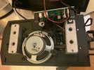
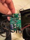
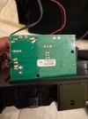
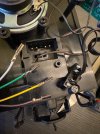
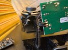
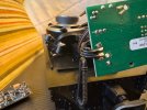
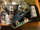
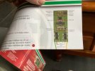
This is the front and back of the board in the lgb 69576 tender with sound. I have an extra massoth 8154001 that i purchased because i thought the loco and tender chips were the same. Unfortunately they aren’t. Can the massoth be installed to make the tender run dcc? I would like to minimize the different number of decoder brands running.
 

Attachments

  • IMG_9612.jpeg
    IMG_9612.jpeg
    365.2 KB · Views: 0
  • IMG_9609.jpeg
    IMG_9609.jpeg
    339.5 KB · Views: 0
I ran extra wires from the loco decoder ( I used a 6 amp Zimo, be sure to use a 2 amp or more decoder) to my powered tender for rear light and motor. I used the original connector for track power. a 5 pin connector was used which allows the plug to be reversed in the socket with no shorts.
(pins 2 and 4 are connected together for one motor lead.
pin 3 for the other motor lead.
1 2 3 4 5
Light motor motor motor light
|----------------|
Can it be done with massoth decoder?
 
Yes, of course..
A decoder is a decoder. As long as it can handle two motors, any make will be suitable.

PhilP
 
Yes, of course..
A decoder is a decoder. As long as it can handle two motors, any make will be suitable.

PhilP
Still a beginner. When you say two motors what do you mean? I thought this tender was a single motor? I thought two motors was when there was wheels in the front and back of a loco, kinda like two tenders together?
 
Still a beginner. When you say two motors what do you mean? I thought this tender was a single motor? I thought two motors was when there was wheels in the front and back of a loco, kinda like two tenders together?
Following on from those using a Zimo decoder:
They are using a decoder located in the loco, and feeding the track pickups from the tender forwards to the loco, and motor outputs back to the tender, along with a line to control the rear light on the tender.

You can have a decoder in the loco and a second decoder in the tender..
These would preferably be from the same manufacturer, and the same model.
You would then set each decoder up separately, and finally give them the same address, so that loco and tender behave as one.

PhilP.
Yes that’s exactly what I want to do. Install a decoder in each. I have two Massoth decoders. I installed one in the loco already, by way of the pins on the decoder. That was like plug and play. In the loco the four wires coming from the motor plug were soldered to 4 separate connections. In the tender the 4 wires are doubled and soldered to 2 connections.
 
Yes that’s exactly what I want to do. Install a decoder in each. I have two Massoth decoders. I installed one in the loco already, by way of the pins on the decoder. That was like plug and play. In the loco the four wires coming from the motor plug were soldered to 4 separate connections. In the tender the 4 wires are doubled and soldered to 2 connections.
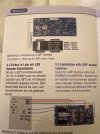
Would I install it according to the top diagram? Would I tap into the four wires coming from the motor block plug? Or separate the doubled wires on the back of the board and then solder together?
 

Attachments

  • image.jpg
    image.jpg
    565.6 KB · Views: 0
Ok 2 ways to do this, a larger decoder in the loco with track power and motor power linked between the loco and tender thus 4 wires joining the two. The other way with 2 smaller decoders one in loco the other in tender again 4 wires joining. I would be tempted to use a small 4 way screw connector block in the tender to connect the wires, this will give you the ability to check things out.

Make sure that you get the connections correct in both cases!
Thanks. The screw terminal is a good idea! Any recommendations? So basically i could take the four wires coming from the decoder with the crimp connections and slide those down over the correct pins and the decoder would basically work? Correct?
 

Attachments

  • IMG_9616.jpeg
    IMG_9616.jpeg
    461.6 KB · Views: 0
Thanks. The screw terminal is a good idea! Any recommendations? So basically i could take the four wires coming from the decoder with the crimp connections and slide those down over the correct pins and the decoder would basically work? Correct
How would i save the factory 4 pin connection plug?
 

Attachments

  • IMG_9617.jpeg
    IMG_9617.jpeg
    611 KB · Views: 0
Thanks. The screw terminal is a good idea! Any recommendations? So basically i could take the four wires coming from the decoder with the crimp connections and slide those down over the correct pins and the decoder would basically work? Correct?
Providing you get the 4 wires and decider correctly matched up. If you get the motor wires wrong not too much of an issue, one part goes one way the other the other. If you mix up the decoder positions you can trash a decoder. Think one rail and get that right, the other decoder wire will then be ok. Where is the factory 4 pin plug, on the loco or tender or both?
 
Providing you get the 4 wires and decider correctly matched up. If you get the motor wires wrong not too much of an issue, one part goes one way the other the other. If you mix up the decoder positions you can trash a decoder. Think one rail and get that right, the other decoder wire will then be ok. Where is the factory 4 pin plug, on the loco or tender or both?
The factory plug is still connected to the “sound board i believe”, this is the sound tender. I removed the factory plug to see if those crimp connectors from the decoder would fit the pins. I would like to leave the sound in there if possible. The factory plug is on the tender. The other wires connected to this board i believe are 2 pass thru ports, speaker, mag. Switch and light. Can i retain the sound?
 
The factory plug is still connected to the “sound board i believe”, this is the sound tender. I removed the factory plug to see if those crimp connectors from the decoder would fit the pins. I would like to leave the sound in there if possible. The factory plug is on the tender. The other wires connected to this board i believe are 2 pass thru ports, speaker, mag. Switch and light. Can i retain the sound?
I assume the four wires coming off the factory 4 wire plug powers the sound board?, the pass thru, speaker, and light?
 

Attachments

  • IMG_9617.jpeg
    IMG_9617.jpeg
    611 KB · Views: 0
I hooked the 4 wires from the decoder straight to the four pins on the motor. I put it on the test track and heard the normal noises when programming. When i put it in the layout, it doesn’t run. Does the original black four pin motor connector need to be hooked back up for the tender to run?
 

Attachments

  • image.jpg
    image.jpg
    931.5 KB · Views: 0
I hooked the 4 wires from the decoder straight to the four pins on the motor. I put it on the test track and heard the normal noises when programming. When i put it in the layout, it doesn’t run. Does the original black four pin motor connector need to be hooked back up for the tender to run?
Ok sounds like you may be a little out of your depth here, no insult in that we all have to start somewhere and DCC plus fitting can be a steep learning curve.

Ok so you have a sound board, is this is not a DCC one? To get this working you would need to connect it to the motor power.

A complete rewire of the connections from wheel pickups to motor on the chassis is required, you could use the 4 pin plug but would need to cut the wires to your sound board. Before that cut you need to understand what wire is what. The Terminal block will be your friend as previously mentioned. Post 14 shows you have the right idea.

Do you have an electric Multimeter to test the electrics? You can use this to test what wires do what, remove the plug and test each of the pins in the chassis. 2 will connect to the wheels 1 each side when the pin and wheel is touched, the other 2 will connect to the motor and give in effect a positive reading via the 2 pins. The pins should be the same for each 4 pin plug but I always test to be sure.

If you do not fancy cutting the plug wire, LGB prongs and new wire will connect to the 4 pins in the chassis, I tend to colour code these to LGB standards. Pic below shows code as used.

Post 12 is pretty much what you need to do duplicated in part in pic below, if you use a terminal block as suggested you should get things correct.

Not sure if you would be keeping loco lights, if so these would be powered from a decoder in here.

The pic in post 12 can be a bit confusing, the 6 wires at the top go to an interface that is only oresent in certain board instances. The motor and pickup colours are duplicated with the BN brown and BL blue are light wires.

I think enough for now, see how you get on and more help available if required.
 

Attachments

  • image.jpg
    image.jpg
    846 KB · Views: 0
Back
Top