AusrailQLD
Registered
Silly question to ask, but what exactly is are these made of?
Been wondering if it's possible to make your own.

Been wondering if it's possible to make your own.


Some of the early overhead was certainly made out of coated steel as it could be soldered if the need arose. Personally I would look at a hard brass rid that could be soldered as it will tarnish nicely outdoors. However if you are using it for outside power contact then that is a different issue.Silly question to ask, but what exactly is are these made of?
Been wondering if it's possible to make your own.

What you are seeking to do is not really possible with the old 3 pin motor blocks. The internal design does not allow for isolating the the one motor contact from the track return in the way you want.Actually, I want to make some to convert old LGB to standard 4 pin setups.
I agree with you that the easier conversion of a 3-pin LGB locomotive to 4-pin functionality is to solder a wire (I use yellow following the LGB wiring color convention) to the + motor terminal. I cut about 1/8th inch off the terminal so that it's isolated from the + track power pin.......no need to bend that terminal which could impede the placement of the top cover. I also solder the wire in the straight up position on the "inner side" of the terminal so the wire can align with the existing pin's exit hole in the top cover. To allow that, I also widen the pin hole in the top cover so it can accommodate both the pin and the new yellow wire. I also double check that the wire is not impeding the top cover's placement from being completely flat. If the yellow wire blocks the mating of the top cover to the motor block, the motor's gears and wheels gears may not align properly causing the motor block to malfunction.What you are seeking to do is not really possible with the old 3 pin motor blocks. The internal design does not allow for isolating the the one motor contact from the track return in the way you want.
With my first 3-pin motor block conversion I did solder a wire to motor contact. The contact was bent and covered with heat shrink to isolate it from the track return pin.
My subsequent conversions were done by making a pigtail with the correct female spade connector covered with shrink wrap. The Märklin part no. is 74995 for a package of 20. The motor contact still needed to be bent a bit but this makes it easier to disconnect and remove the motor when needed.
Actually, I never said soldering the connection is the easier DCC conversion. From my experience I recommend using the female spade connector on a pigtail for conversions. I've converted a LGB 2045 Ge 2/4 box cab, a 2046 Hg 2/2 rack loco, and a 2070D U Lok (clamshell motor block) using a pigtail on the motor's track return connector. I drilled a small hole in the top motor block cover between the existing pins for the pigtail lead to emerge. I've not encountered any problem with the lead inhibiting the motor block cover being correctly reinstalled or the lead interfering with the internal gears. All three locos have many hours on them without any issues related to the motor conversion. I do use a yellow lead on the motor pigtail in keeping with the LGB 4 pin motor block wire color convention.I agree with you that the easier conversion of a 3-pin LGB locomotive to 4-pin functionality is to solder a wire (I use yellow following the LGB wiring color convention) to the + motor terminal. I cut about 1/8th inch off the terminal so that it's isolated from the + track power pin.......no need to bend that terminal which could impede the placement of the top cover.
You indicated: "I recommend using the female spade connector on a pigtail for conversions." Could you post a photo of this connector.......not sure what you are using.Actually, I never said soldering the connection is the easier DCC conversion. From my experience I recommend using the female spade connector on a pigtail for conversions. I've converted a LGB 2045 Ge 2/4 box cab, a 2046 Hg 2/2 rack loco, and a 2070D U Lok (clamshell motor block) using a pigtail on the motor's track return connector. I drilled a small hole in the top motor block cover between the existing pins for the pigtail lead to emerge. I've not encountered any problem with the lead inhibiting the motor block cover being correctly reinstalled or the lead interfering with the internal gears. All three locos have many hours on them without any issues related to the motor conversion. I do use a yellow lead on the motor pigtail in keeping with the LGB 4 pin motor block wire color convention.
I soldered the motor connections on the first loco I converted, a 2040 Crok. I now wish I had used spade connectors on this one too.
My original LGB 2040 conversion was done following this guide from Massoth. For me, the spade lug approach I've since adopted works better.Have a look at this page, found it a couple of years ago:
Could you show us a photo of the spade lug connector........still not sure what you're using?My original LGB 2040 conversion was done following this guide from Massoth. For me, the spade lug approach I've since adopted works better.
Sure, here's my 2045 conversion, and a pic of the Märklin crimp-on spade connectors. I should mention that I solder the connector to the pigtail wire in addition to crimping just to give more strength. My heat shrink job is not the prettiest here and completely covers the spade connector. This was my first use of the spade connectors. (And the easiest loco to open up for pics.) Looking closely you can see how the heat shrink insulates the motor from the WS (white) pin. This pigtail was made with very stiff wire. I've since started using 24 awg silicone insulated wire from BNTECHGO for my decoder wiring work. A pic of the label for yellow is shown.Could you post a photo of this connector.......not sure what you are using.
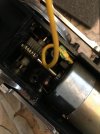
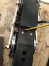
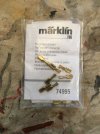
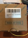
Thanks for sharing, phils2um, your technique for converting an LGB motor block from 3-pin to 4-pin functionality. A photo of how I do it is below.......just reduce the motor terminal length and then solder on the 22 AWG yellow wire. Some hobbyists actually install a fourth pin instead of a wire.......too much work for my tastes!Sure, here's my 2045 conversion, and a pic of the Märklin crimp-on spade connectors. I should mention that I solder the connector to the pigtail wire in addition to crimping just to give more strength. My heat shrink job is not the prettiest here and completely covers the spade connector. This was my first use of the spade connectors. (And the easiest loco to open up for pics.) Looking closely you can see how the heat shrink insulates the motor from the WS (white) pin. This pigtail was made with very stiff wire. I've since started using 24 awg silicone insulated wire from BNTECHGO for my decoder wiring work. A pic of the label for yellow is shown.
View attachment 294657 View attachment 294658 View attachment 294659 View attachment 294660
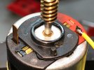
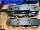
That is also the way I do it, works just fine.Thanks for sharing, phils2um, your technique for converting an LGB motor block from 3-pin to 4-pin functionality. A photo of how I do it is below.......just reduce the motor terminal length and then solder on the 22 AWG yellow wire. Some hobbyists actually install a fourth pin instead of a wire.......too much work for my tastes!
View attachment 294778View attachment 294779
