MER Vehicles

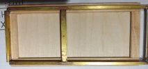
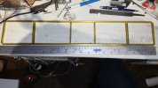
Finally I have made a proper start on my first Manx Electric Railway vehicle, loco Number 23.

That's the chassis main frames assembled, next will be the body to go on top before I do any more work to the chassis.

The drawings I purchased are a little under scale hence the chassis being a wee bit longer than that on the drawing.

David
 

Attachments

  • 20211217_211620.jpg
    20211217_211620.jpg
    309.1 KB · Views: 0
Finally I have made a proper start on my first Manx Electric Railway vehicle, loco Number 23.

That's the chassis main frames assembled, next will be the body to go on top before I do any more work to the chassis.

The drawings I purchased are a little under scale hence the chassis being a wee bit longer than that on the drawing.

David
Glad to see a start being made: I always fancied making a model of the original in steeple cab form. The brass frame will lend low-down weight and give a rigid structure: I made my first IOM carriage that way: the main challenge was getting enough heat to solder the parts without distorting the frame. Mine did distort, though I was able to tweak it straight; subsequent builds have relied on the body to provide stiffness -not so easy with the open wagon ends on No23.

IP Engineering produce whitemetal strap hinges, in 'static' and working forms. I made my own ones in brass for the latest H wagons, but they were a pig to get aligned, resulting in wonky drop-down doors...
Use on on Carr's, lower melting point solders
 
Glad to see a start being made: I always fancied making a model of the original in steeple cab form. The brass frame will lend low-down weight and give a rigid structure: I made my first IOM carriage that way: the main challenge was getting enough heat to solder the parts without distorting the frame. Mine did distort, though I was able to tweak it straight; subsequent builds have relied on the body to provide stiffness -not so easy with the open wagon ends on No23.

IP Engineering produce whitemetal strap hinges, in 'static' and working forms. I made my own ones in brass for the latest H wagons, but they were a pig to get aligned, resulting in wonky drop-down doors...
I have a heavy duty soldering station which allows me to set the exact temperature I want at the tip, it also tells me what the temperature at the soldering tip, I think its rated at around 150w, the only time I've had any problems with heat is if I've used steel blocks for alignment.

I use Duncan flux for everything, its especially good white low melt solder, and I use 3 different temperature rated Duncan solder's.

The angle brackets were RSU soldered to the side channels before fitting the end beams with a soldering iron.
No twist and I only needed to adjust one of the truck cross beams once everything else was

Unfortunately the IP brackets are not correct so not unexpectedly I'll need to make my own.

David
 
Last edited:
Ooh er missus - that's doubly difficult :worried::worried:
I have a plan, it's only a plan, or maybe just an idea, its possibly just a thought though.

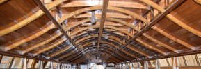
For the 7/8ths Groudle Glen coach roofs I managed to bend some bass wood around a ply wood disk former with a grove cut in the edge to bend the roof beams using steam.
My thought is that I might be able to make a male/female former to bend these roof parts, a three part former the first pair to form the middle part and a third part to form the outer curves. This method would unfortunately mean more wastage of material than I like to accept but its the only way I can think of short of cutting each individual cross member from a sheet which isn't really what I want to do.

Also unfortunate, no drawings exist of the trams which had these roofs so I'll also need to produce a drawing myself.

But I digress, No. 23 first.

David
 
:h:
T'is a thing of beauty, and craftsmanship.

Smacks of the boat-builders craft, to me? - Which would make sense, if they were built on the Isle..
 
Just thinkibg this through, though it is nice to replicate the roof detail but when is it ever seen? For myself on any scratch projects and that has included Railcars I have used a flat roof thus allowing the limited round space above to be used for Batteries and other RC equipment.
 
I have a plan, it's only a plan, or maybe just an idea, its possibly just a thought though.

For the 7/8ths Groudle Glen coach roofs I managed to bend some bass wood around a ply wood disk former with a grove cut in the edge to bend the roof beams using steam.
My thought is that I might be able to make a male/female former to bend these roof parts, a three part former the first pair to form the middle part and a third part to form the outer curves. This method would unfortunately mean more wastage of material than I like to accept but its the only way I can think of short of cutting each individual cross member from a sheet which isn't really what I want to do.

Also unfortunate, no drawings exist of the trams which had these roofs so I'll also need to produce a drawing myself.

But I digress, No. 23 first.

David
Definitely a labour of love.

I made a US Combine from wood, but I'm a devout bodger and professional cheat, so it looks OK on the outside, but the interior is not for public consumption :tmi::tmi:
 
Just thinkibg this through, though it is nice to replicate the roof detail but when is it ever seen? For myself on any scratch projects and that has included Railcars I have used a flat roof thus allowing the limited round space above to be used for Batteries and other RC equipment.
Its one of those "I will know" things, I don't disagree with your comment but for me it needs to be correct, folk tend to call it an Elvy'ism. I have also said from day 1 that I want to stick to the fine scale modelling I have been trying to achieve in 7mm scale in the larger scale models, yes I am making life a bit more challenging than it possibly needs to be but it keeps me happy trying to find solutions to challenges.

One of the things I plan to trial with No. 23 is using a small receiver and running off the overhead for power, to overcome dirt on the wire and rails causing intermittent power loss a capacitor will hopefully help, I've had some good discussions with Phil at RC Trains, if all else fails I just need to revert back to batteries. I would like to say its part of the fun of the hobby, but sometimes I end up getting bits n bobs I end up not needing, but hey it gives me something to do and sort of keeps me out of mischief, to a point.
I have proved the Locoremote system works fine, the downside for me and the MER trams is that its a bit bulky to try and hide, hence looking at an alternative.

In the 8 months I have been working in the larger scale, I have learnt a lot and not made too many fubars or wasted much money, that for me is a success. and now I am waffling.

David
 
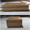
Well that's the first open wagon body trial assembled.

The internal strapping I am now hoping to have 3D resin printed, the outer strapping will need to be made from brass as I want the side to drop, the bolt/nut heads I am also hoping to have 3D printed.

The first of anything always takes the longest and this has definitely been true of this body, I now have a set of dimensions which work and look correct so the second end open wagon body should go a little quicker.
The open wagon bodies fitted to MER 23 were the same as the standard open wagon. So a couple of these could follow.

Anyhow, progress is progress and I have progressed if slower than I'd hoped.

David
 

Attachments

  • 20211228_231932.jpg
    20211228_231932.jpg
    201.9 KB · Views: 0
My first fubar with No. 23, how I fix the wagon body floor to the chassis, less rush and more thinking in future.

I should have put the fixing bolts through the timber which supports the floor planks, i am now pondering how to attach some fixing bolts to the underside of the floor. Present thinking is a piece of scrap flat brass with a bolt soldered to it fixed in place with uhu glue to the underside of the floor, with a second piece of brass soldered to the chassis frame which the bolt can pass through and the body held securely to the frame, I hope that all makes sense.

Happy to receive any other ideas folk might have.

David
 

Attachments

  • 20211229_175523.jpg
    20211229_175523.jpg
    146.7 KB · Views: 0
I would be tempted to saw the head off the screw, drill a small hole in the bottom of the chassis and glue the resulting threaded bar in place.

It will be much flatter than the thickness of the brass, let alone trying to solder in the screw.
 
I'm not sure quite what you are after; an authentic, i.e. actual fixing, or an after the event fixing that looks the part? If the latter, I would suggest using a pin driver on the timber, which will create a domed shape in the wood, defined by a crisp circle: which will look, to all intents and purposes, like a coach bolt head...
 
Some experimenting today, I now think my easiest option is to simply solder a 6mm wide strip inside either side of the chassis and fit a self tapping screw screwed directly in to the wood from the underside.

I time permits tomorrow, I'll get this done and post a photo.

For every challenge their is a solution, its finding the best solution for the circumstance which can delay things while also needing consultation with the wider audience to generate movement in the grey cells.


David
 
For every challenge their is a solution...which can delay things...
Prototyping takes time; the only pay-offs are that a) once you've done it, any duplicate model will be quicker to make and b) you will be increasing your range of modelling skills and experience. As you are likely to make only one MER No.23, the second point is more probable in this case. Mind you, if you do want to make a second one, I'd be more than happy to give it a home! :D
 
Prototyping takes time; the only pay-offs are that a) once you've done it, any duplicate model will be quicker to make and b) you will be increasing your range of modelling skills and experience. As you are likely to make only one MER No.23, the second point is more probable in this case. Mind you, if you do want to make a second one, I'd be more than happy to give it a home! :D
Nope I can't see me building a second No. 23 except possibly the wee loco itself.

While building the wagon bodies for No. 23 I have kept in mind that the wagon bodies are to the standard open wagon design, so two standard open wagons should follow using materials left over from No. 23.

What I want to build is not a rivet counter perfect model but a nice fine scale model with a level of detail that gives me satisfaction of building a nice model, as accurate as my skills permit and information is available to someone not living on the island or having been there for a good number of years.

Let's wait and see what comes out of the end end of this build, you never know as skills improve I might say this No. 23 was a good learning curve now let's build one I would be happier with, heck I don't even know what Monday will bring, that's the fun I am finding with this modelling scale.

Sun lin fai lok when it comes.

David
 
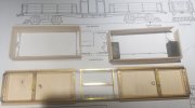
A lot later in the day than planned but timber work for both wagon bodies is complete, and a wee update to the chassis.

Wagon body floors have been screw fitted in place utilising new cross members.

Since find out a bit more information about the cab floor I have also added a bit more support for the cab floor.

Now all the seasonal domestic distractions have concluded I can hopefully get back to some undisturbed modelling ;-)

20220102_003758.jpg

David
 
A wee bit more progress with the wagon bodies for MER 23.

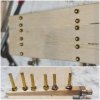
You need to keep in mind the pins in the picture are 1.5mm dia. and the photo has been significantly zoomed to show what the finish looks like.

Yes one of the stanchions moved during drilling, this end will be place in the centre next to the cab :-)

Although the wood is a little burnt on the first stanchion I soldered the nut to the rivet the second one looks acceptable to me, I just need to keep the RSU time to a minimum and avoid over cooking things.

The nuts are actually just 1mm long pieces of 2.3mm square box section, I couldn't find a supplier for square nuts (yes children you can have a laugh) which the prototype has, so if I had gone with threaded bolts I'd have need to file every nut which I didn't relish.

This is my solution to the rivet challenge, £ wise it was this or 12ba bolts n nuts at 5-6 x the price, once cleaned up and painted I think I'll be happy with my chosen solution.

20220108_235917.jpg

David
 
Back
Top