You are using an out of date browser. It may not display this or other websites correctly.
You should upgrade or use an alternative browser.
You should upgrade or use an alternative browser.
My ÖBB 399 / NÖLB Mh
- Thread starter bensch_55
- Start date
bensch_55
Registered
So, today the first batch of the running gear parts have been printed. Nothing is perfect but pretty solid for a first run:
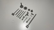
It's hardly visible on the picture, but even the 1,5mm small hex nuts are printed in razor sharp detail. Tomorrow I will clean them fully up and take some measurments, after that a first test on the chassis will follow.
Wish you a nice evening,
Ben

It's hardly visible on the picture, but even the 1,5mm small hex nuts are printed in razor sharp detail. Tomorrow I will clean them fully up and take some measurments, after that a first test on the chassis will follow.
Wish you a nice evening,
Ben
bensch_55
Registered
Hello everyone,
it took some time but progress has been made. The parts were cleaned up, measured for reference and the first "loose" trial assembly has been finished.
For the very first prints I'm happy with the results. There were a few issues with certain tolerances but those areas are easy to modify. Some other changes will be made to improve the assembly process.
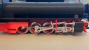
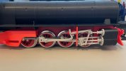
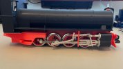
In the meantime I also made the decision which model and era I want to replicate with the first model. Right now, the chassis is red like all of them were in the "ÖBB-Era" (around 1970-2000). Since the filament will never exactly match the colour of the LGB chassis, painting will always be necessary. This brought me to the decision to choose the colour scheme of the most recent restored machines, all black (and in case of Mh.3 & 4) with only red wheels and details on the valvegear:
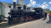
However, as this won't be the only model for the collection, I'm already trying to decide between 399.01 & .02 for the next one
it took some time but progress has been made. The parts were cleaned up, measured for reference and the first "loose" trial assembly has been finished.
For the very first prints I'm happy with the results. There were a few issues with certain tolerances but those areas are easy to modify. Some other changes will be made to improve the assembly process.


In the meantime I also made the decision which model and era I want to replicate with the first model. Right now, the chassis is red like all of them were in the "ÖBB-Era" (around 1970-2000). Since the filament will never exactly match the colour of the LGB chassis, painting will always be necessary. This brought me to the decision to choose the colour scheme of the most recent restored machines, all black (and in case of Mh.3 & 4) with only red wheels and details on the valvegear:

However, as this won't be the only model for the collection, I'm already trying to decide between 399.01 & .02 for the next one
bensch_55
Registered
Hey guys,
I know it's been some time since my last post, but life just got a bit in the way of working on this project. Fortunately I was able to pick it back up and make some progress.
So, since the last update I implemented the findings of the valve gear into the 3D model, printed it again and checked the fitment. The parts fit a lot better now right from the printbed.
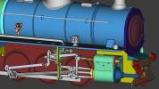
Next there was some work done to the details around the boiler and tender: Oil pumps, electrical boxes, rivets, etc..
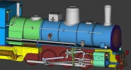
I also have two issues I could use some help from your experience
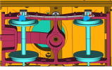
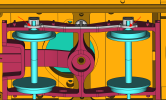
1) As of now, the tender boogie is one piece with a detail piece glued onto it. The issue is, afterwards the axle can't be removed as it gets physically locked in place.
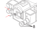
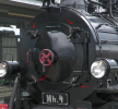
2) The prototype uses four latches to fix the boiler door in place. I know LGB models have this function as well but I yet have to figure out how to implement it on my model.
Any help, suggestions and ideas are greatly appreciated.
And with that, I hope you have a nice evening,
Ben
I know it's been some time since my last post, but life just got a bit in the way of working on this project. Fortunately I was able to pick it back up and make some progress.
So, since the last update I implemented the findings of the valve gear into the 3D model, printed it again and checked the fitment. The parts fit a lot better now right from the printbed.
Next there was some work done to the details around the boiler and tender: Oil pumps, electrical boxes, rivets, etc..

I also have two issues I could use some help from your experience
1) As of now, the tender boogie is one piece with a detail piece glued onto it. The issue is, afterwards the axle can't be removed as it gets physically locked in place.

2) The prototype uses four latches to fix the boiler door in place. I know LGB models have this function as well but I yet have to figure out how to implement it on my model.

Any help, suggestions and ideas are greatly appreciated.
And with that, I hope you have a nice evening,
Ben
Attachments
Make the boiler door latches out of brass bar /tube...I realise that your printing it, but sometimes it is easier to use brass?
As for the tender wheels , can they clip into the boddy instead of the solid bar underneath the axle on both sides , cut it back on one side ?
As for the tender wheels , can they clip into the boddy instead of the solid bar underneath the axle on both sides , cut it back on one side ?
bensch_55
Registered
Rhinochugger
Retired Oik
Don't forget to allow some sideways movement in the tender wheels. Irrespective of what curves you're aiming to use, in our scale bogie wheels need some sideplay as a matter of courseHey guys,
I know it's been some time since my last post, but life just got a bit in the way of working on this project. Fortunately I was able to pick it back up and make some progress.
So, since the last update I implemented the findings of the valve gear into the 3D model, printed it again and checked the fitment. The parts fit a lot better now right from the printbed.
Next there was some work done to the details around the boiler and tender: Oil pumps, electrical boxes, rivets, etc..
View attachment 333611
I also have two issues I could use some help from your experience
1) As of now, the tender boogie is one piece with a detail piece glued onto it. The issue is, afterwards the axle can't be removed as it gets physically locked in place.
View attachment 333612
2) The prototype uses four latches to fix the boiler door in place. I know LGB models have this function as well but I yet have to figure out how to implement it on my model.
View attachment 333613
Any help, suggestions and ideas are greatly appreciated.
And with that, I hope you have a nice evening,
Ben
bensch_55
Registered
You are absolutely right. I designed mine with some measurments that I took from an LGB boogie and it worked without problems on the first runs around the layout. The assembly wouldn't bother me too much as it is right now, but with the thought of releasing it as a set I think it needs to be possible to swap the axles more easily.
My early LGB 2080 only has 2 moving dogs on the opposite side to the hinge. As for bogies, why not replicate an LGB bogie to have 2 side-frames with a central swivelling bit and screw the side-frames in place, that will resolve your wheel change requirements..Hey guys,
I know it's been some time since my last post, but life just got a bit in the way of working on this project. Fortunately I was able to pick it back up and make some progress.
So, since the last update I implemented the findings of the valve gear into the 3D model, printed it again and checked the fitment. The parts fit a lot better now right from the printbed.
Next there was some work done to the details around the boiler and tender: Oil pumps, electrical boxes, rivets, etc..
View attachment 333611
I also have two issues I could use some help from your experience
1) As of now, the tender boogie is one piece with a detail piece glued onto it. The issue is, afterwards the axle can't be removed as it gets physically locked in place.
View attachment 333612
2) The prototype uses four latches to fix the boiler door in place. I know LGB models have this function as well but I yet have to figure out how to implement it on my model.
View attachment 333613
Any help, suggestions and ideas are greatly appreciated.
And with that, I hope you have a nice evening,
Ben
bensch_55
Registered
Hey guys,
sorry for the radio silence but I'm the kind of guy who likes to dig into a problem until it is solved - and thanks to a friend I think I (or we?) have, so here it is:
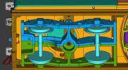
The whole bogie got split along the center line. This allows all the details to be printed in one go and provides an easy option to change the axles.
But, since a solution is only a good solution when it solves more than one problem, this also allows for an improved joint to fix the bogie to the frame: A ball joint! I still have to play around with some designs and will update you once it is finished.
In the meantime I also chipped away on various little details, as well as finally finding some good primer and paint that provides the look I am after. Another friend also had the LGB U smokebox latches I was searching for. They will fit the build but since they are really hard to come by at the moment I am considering designing and printing my own.
So that is all for now, I will keep you updated and hope you have a great weekend!
Ben
sorry for the radio silence but I'm the kind of guy who likes to dig into a problem until it is solved - and thanks to a friend I think I (or we?) have, so here it is:

The whole bogie got split along the center line. This allows all the details to be printed in one go and provides an easy option to change the axles.
But, since a solution is only a good solution when it solves more than one problem, this also allows for an improved joint to fix the bogie to the frame: A ball joint! I still have to play around with some designs and will update you once it is finished.
In the meantime I also chipped away on various little details, as well as finally finding some good primer and paint that provides the look I am after. Another friend also had the LGB U smokebox latches I was searching for. They will fit the build but since they are really hard to come by at the moment I am considering designing and printing my own.
So that is all for now, I will keep you updated and hope you have a great weekend!
Ben
bensch_55
Registered
So, small update on that boogie front:
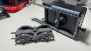
The whole boogie concept was reworked AGAIN in order to get to this solution. It's relatively easy to print, looks decent and mounting the boogie to the tender is as easy as snapping it in place on the ball joint.
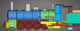
Besides this there was also some work on the accessories such as the brake and vacuum reservoir on the left side of the engine:
There was also a lot of time spent around other small details that I will show off once I got them printed. All in all a lot of work went into lots and lots of small things and details, I hope it will pay off in the end.
With that I wish you a nice evening,
Ben
The whole boogie concept was reworked AGAIN in order to get to this solution. It's relatively easy to print, looks decent and mounting the boogie to the tender is as easy as snapping it in place on the ball joint.

Besides this there was also some work on the accessories such as the brake and vacuum reservoir on the left side of the engine:

There was also a lot of time spent around other small details that I will show off once I got them printed. All in all a lot of work went into lots and lots of small things and details, I hope it will pay off in the end.
With that I wish you a nice evening,
Ben
HobbitFertang
Registered
Impressive work!
bensch_55
Registered
Thank you all for the kind words, it's always motivating to see your reactions!
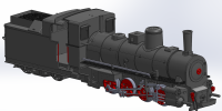
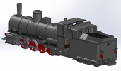
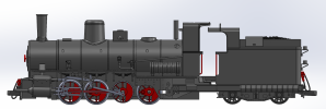
I hope all of you had a nice Christmas and are already enjoying your holidays. I have still been busy until the 24th so I'm able to show you something close to the finished model. There is still a lot of little details missing but the majority of parts are there and I will finally be able to shift the focus on the interior of the locomotive. So with that said, here is the current status in the proper colour:
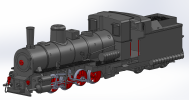
As always, don't hesitate to let me know what you think and what you think could still be improved.
Again, Merry Christmas to all of you,
Ben
I hope all of you had a nice Christmas and are already enjoying your holidays. I have still been busy until the 24th so I'm able to show you something close to the finished model. There is still a lot of little details missing but the majority of parts are there and I will finally be able to shift the focus on the interior of the locomotive. So with that said, here is the current status in the proper colour:


As always, don't hesitate to let me know what you think and what you think could still be improved.
Again, Merry Christmas to all of you,
Ben
Attachments
It has on one of the sketchesbensch_55 just one minor observation, the rear driven wheel (forth axel) should not have a connecting rod on it?
Other than that it look very good indeed
bensch_55
Registered
Hello Jimmy,should not have a connecting rod on it?
The connecting rods were a bit of an afterthought as I used the LGB ones until now, but for the kit we‘re creating specific ones
bensch_55
Registered
Hey everyone,
first of all, I hope you had nice holidays and a good start into the new year
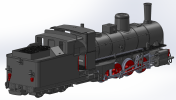
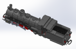
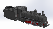
Although I had to go through the yearly "holiday marathon", trying to see most of the family, I did have some time to work on the 399. The CAD model received some additional details and is more or less in its finished state now:
After refining the model, printing the first "proper" parts could begin. As the ASA material became more and more of a hassle with each part, the decision was made to switch to PETG. Once everything was printed it was time for paint - and I just want to add, I'm not great with paint - but I think it turned out pretty ok.
With everything dipped in some colour, final assembly could begin as well as testing all the electrics. Assembly went mostly smoothly, apart from some minor stupid mistakes from my side and the valve gear rivets testing my patience, but it got there in the end:
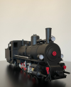
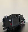
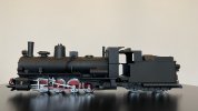
Some details like the numbers and the hand rail along the boiler still have to be added but this is as far as I got yesterday evening. Once everything is done I can pack her up and get on some tracks.
Have a nice day,
Ben
first of all, I hope you had nice holidays and a good start into the new year
Although I had to go through the yearly "holiday marathon", trying to see most of the family, I did have some time to work on the 399. The CAD model received some additional details and is more or less in its finished state now:


After refining the model, printing the first "proper" parts could begin. As the ASA material became more and more of a hassle with each part, the decision was made to switch to PETG. Once everything was printed it was time for paint - and I just want to add, I'm not great with paint - but I think it turned out pretty ok.
With everything dipped in some colour, final assembly could begin as well as testing all the electrics. Assembly went mostly smoothly, apart from some minor stupid mistakes from my side and the valve gear rivets testing my patience, but it got there in the end:


Some details like the numbers and the hand rail along the boiler still have to be added but this is as far as I got yesterday evening. Once everything is done I can pack her up and get on some tracks.
Have a nice day,
Ben

