You are using an out of date browser. It may not display this or other websites correctly.
You should upgrade or use an alternative browser.
You should upgrade or use an alternative browser.
NOW THE BATTERY WORK BEGINS Train Line Pffifi 6101 and Mallett Break Down Diagrams any one have a link please? Link provided thanks.
- Thread starter dunnyrail
- Start date
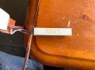
Oh goodness me, what a question. I got the setup ready made from Steve at Fosworks. I think the resistance is about as big as you may be able to get, tis the grey/light coloured thing. It does get very hot if there is a lot of juice still in the battery.Very useful advice, Jon. Thank you for sharing it. What size of resistor did you use?
That is a 6.8 Ohm resistor, but the main criterion is the power it can dissipate..
You can use something like a 21W car brake light bulb.
Whatever you use, it must be supported in free-air. - It will get warm (minimum) but more likely HOT!
Don't leave it unattended, and check the battery pack is not getting more than warm to the touch.
PhilP
You can use something like a 21W car brake light bulb.
Whatever you use, it must be supported in free-air. - It will get warm (minimum) but more likely HOT!
Don't leave it unattended, and check the battery pack is not getting more than warm to the touch.
PhilP
I mounted the vero board on some ply using araldite and the board is normally held aloft on crock clips. Certainly the battery getting warm can be an issue so I set an egg timer for 4 minutes to look at it to see how the battery reduction is going. The lamp gives a clue going out when fully flat and dimmer as power declines.That is a 6.8 Ohm resistor, but the main criterion is the power it can dissipate..
You can use something like a 21W car brake light bulb.
Whatever you use, it must be supported in free-air. - It will get warm (minimum) but more likely HOT!
Don't leave it unattended, and check the battery pack is not getting more than warm to the touch.
PhilP
Rhinochugger
Retired Oik
Uh oh, I think I've worked out how you do it 

My much abused Pfiffi was in trouble at the Thursday operating day, it lost sound sort of intermittently so it had to go into the workshop for investigation. My initial thoughts were speaker not anything else and such proved to be the case. However on pulling apart a loose wire suggested that may be at fault but in the end it was trashed not working at all when wired up to a test plus and tested ignoring the volume pot on the dome. So a replacement speaker (of suitable electrical requirement) sourced from my spares, wired up and tested sound returned, joy. But this lead to much hassle pulling the thing apart so the pics below show the way. White Plasticard strips show the vital screws to undo.
Heads up though do not undo chassis, there are no hidden screws to get into the chip or inside the boiler. Note also there will be extra wires in places seen in the pics plus switches used for my battery conversion of this loco. Take great care there are many small weak bits that are easily broken off…..
1st up is Cab removal facilitated by 4 screws indicated by the 2 bits of plastic at the rear 2 screws in similar position each side.
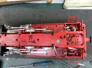
When removing the cab be careful of the plug that connects the rear lights, gently pull this out. This will reveal the 2 screws (1 each side) indicated by white plastic again that release the front cab plate that slides off.
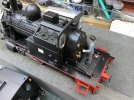
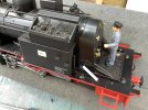
Finally undoing the 2 silver Hex type screws will release the tanks, these contain big lumps of weight that are held in place by those strong screws.
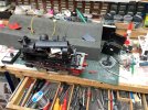
Obviously rebuild is the reverce of these steps.
Heads up though do not undo chassis, there are no hidden screws to get into the chip or inside the boiler. Note also there will be extra wires in places seen in the pics plus switches used for my battery conversion of this loco. Take great care there are many small weak bits that are easily broken off…..
1st up is Cab removal facilitated by 4 screws indicated by the 2 bits of plastic at the rear 2 screws in similar position each side.

When removing the cab be careful of the plug that connects the rear lights, gently pull this out. This will reveal the 2 screws (1 each side) indicated by white plastic again that release the front cab plate that slides off.


Finally undoing the 2 silver Hex type screws will release the tanks, these contain big lumps of weight that are held in place by those strong screws.

Obviously rebuild is the reverce of these steps.

