Piko 35040 RC help

Mike Whitcomb

Registered
Country flag
I just purchased several of the Piko 35040 rc units. I attempted to install it in one of my Piko BR199's using track power. I followed all the instructions for a "parallel" set up using the piko board which came with the train. This way I wouldn't have to mess with all the directional lights. I tested it on the bench with a 4' piece of track and an old power source i found (might even be for an HO set up) It worked great, nice slow steady progression of speed, great response. So now let's try it on the layout. I clean all the tracks run my little LGB shunter around to test everything it all looks good. I am using a DC PWM Motor controller, reversible with 24v max w/40 amps for my power to the layout. I put the Piko BR 199 on the layout and using the supplied little remote off she goes. OK, not as fast as before the installation but its decent. After a few laps and maybe 10 min of run time it starts to pick up speed. So I'm thinking maybe its breaking in ok, it goes in both directions ok. Then it stops and smokes (no smoke unit installed) I shut it down. Can't tell where the smoke originated from. Try to start it up again, moves 6 inches then shuts down, I bring it back to the bench on the smaller power source, does the same thing 6 inches and shuts down. Took it apart and noticed what could be some burned off insulation on a wire between boards for the motors. Took the rc unit out installed in a battery loco and works like a dream. The wire that had the insulation melted off was a "solid strand" wire, not a multi strand wire. Too much resistance? 2 motors on this Harze Kamel. Any input would help.
 
We talk a lot on here about the escape of Magic Smoke, but it's not all that often that someone is unfortunate enough to actually witness it! :(

No idea what the problem may be, but it might help others to assist in the diagnosis if you could post some pics of the inside of the loco and the damaged wiring, maybe someone can then figure out where it goes and what might have happened to melt it?

Afraid that I've never had my Harzkamel apart, it came already fitted with an Uhlenbrock decoder and various gizmos such as powered uncouplers and a flashing RC shunting light, so I've left well alone and have no idea what it looks like inside....

Jon.
 
no the solid wire would not cause a problem because it is solid.

Pictures or a wiring diagram would help people help you. You only describe a wire between the boards for the motors.

Interestingly, I don't think any stock wiring is solid wire.

Greg
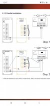
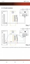
The solid wire was not stock, it was used as the red wire in the bottom diagram that shows a red and blue wire for m1 and m2Screenshot_20200924-124722_Chrome.jpg
 
Which connectors are you feeding power into the Piko unit, and what voltage were you pumping into the track?

You should have been using the 'A' set of connectors, rated at 12-22V Ac or DC.


I am trying to get confirmation that this configuration will be happy with a PWM supply.
But it actually sounds like you had a wiring problem within the loco?

PhilP.
 
Alarm bells ringing!
You say a 'parallel' installation? - Does this involve you driving the motors from the RC, but having track power to the original electronics in the loco for 'everything else'?

Can you point me at the document with reference to this 'parallel installation' please?

PhilP.
 
Which connectors are you feeding power into the Piko unit, and what voltage were you pumping into the track?

You should have been using the 'A' set of connectors, rated at 12-22V Ac or DC.


I am trying to get confirmation that this configuration will be happy with a PWM supply.
But it actually sounds like you had a wiring problem within the loco?

PhilP.
The power supply coming from the trucks were going directly into the switch as Input "A" the track voltage varied as i tested it, max could have been 24v
 
Alarm bells ringing!
You say a 'parallel' installation? - Does this involve you driving the motors from the RC, but having track power to the original electronics in the loco for 'everything else'?

Can you point me at the document with reference to this 'parallel installation' please?

PhilP.
Its shown here:
 

Attachments

  • Screenshot_20200924-124722_Chrome.jpg
    Screenshot_20200924-124722_Chrome.jpg
    106.8 KB · Views: 0
Hmmm...

Don't you love it when the instructions contradict themselves?

Specs.
Power supply: 7 - 24 V DC / 6 - 18 V AC max. current: 3A

Wiring:
Voltage from track (Rail contact loco) 12 - 22 V AC / DC INPUT A
Battery 7-24 V DC INPUT B

Poor.. But I think a red-herring in this particular case?
 
The power supply coming from the trucks were going directly into the switch as Input "A" the track voltage varied as i tested it, max could have been 24v

Input A is good..
24V is possibly not..

As it is a PWM supply, I would not exceed 18V unless 'we' can get clarification (I have already asked) from Piko about the supply voltages and whether a PWM supply is OK.

PhilP.
 
Hmmm...

Don't you love it when the instructions contradict themselves?

Specs.
Power supply: 7 - 24 V DC / 6 - 18 V AC max. current: 3A

Wiring:
Voltage from track (Rail contact loco) 12 - 22 V AC / DC INPUT A
Battery 7-24 V DC INPUT B

Poor.. But I think a red-herring in this particular case?
I have only seem videos of this being used with a battery set up, which I did in another lico with this particular unit to see if I damaged it. It worked great on battery power.
 
Input A is good..
24V is possibly not..

As it is a PWM supply, I would not exceed 18V unless 'we' can get clarification (I have already asked) from Piko about the supply voltages and whether a PWM supply is OK.

PhilP.
Thanks, I have a 12v power supply that I can use. Not looking for speed just a realistic shunting speeds for my herd of Kamels, lol.
 
Mike,
I think you probably have a wiring problem within the loco? - The unit works fine in a battery installation, so it must be down to this 'parallel installation' or the wiring within the loco, I reckon.

** Can you point me to the source of information for this installation, please? **
(Found it! - Had not gone far enough in the 35040 manual)

PhilP.
 
Last edited:
Mike,
I think you probably have a wiring problem within the loco? - The unit works fine in a battery installation, so it must be down to this 'parallel installation' or the wiring within the loco, I reckon.

** Can you point me to the source of information for this installation, please? **

PhilP.
I used the diagram that came with the RC unit Which is posted in this thread
 
I used the diagram that came with the RC unit Which is posted in this thread

I found it.. - Had not gone far enough down the RC manual. :rolleyes:

Would the burnt-wire be one of those from the receiver to the analogue board? - A picture would be good. :)
 
I was waiting for the identification of the burnt wire.

I'm assuming "parallel" installation allows track or battery power?

Greg
Parallel installation allows you to use the existing board for the directional lighting without having to transfer all that to the new receiver board. It can be used with eithther track power or battery power
 
Yes, it is the red wire in the bottom diagram. I have no pics at thistime

It could just be the wire in question was to light (in gauge) burnt-out, and was touching the weight in the loco?? - The weight is normally used as a heatsink, and quite often the components are not insulated.


So voltage from the track ONLY connects into the switch A connections, and then the 'motor' outputs of the receiver feed into the track inputs of the Analogue Board?
 
Back
Top