Piko 35040 RC help

It could just be the wire in question was to light (in gauge) burnt-out, and was touching the weight in the loco?? - The weight is normally used as a heatsink, and quite often the components are not insulated.


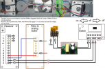
So voltage from the track ONLY connects into the switch A connections, and then the 'motor' outputs of the receiver feed into the track inputs of the Analogue Board?
Are used a heat sink and insulated the receiver to make sure there were no shorts
 
It could just be the wire in question was to light (in gauge) burnt-out, and was touching the weight in the loco?? - The weight is normally used as a heatsink, and quite often the components are not insulated.


So voltage from the track ONLY connects into the switch A connections, and then the 'motor' outputs of the receiver feed into the track inputs of the Analogue Board?
Yes track power to the switch then from the switch to the RC board then over to the analog board Then to the motors
 
so where is the battery in the diagram? Also, which red wire burned, the solid one, or the dashed one?

Greg
No battery in this configuration only track power. It would be the red dashed line. I also did find a slightly melted wire coming off the front truck from a track lead that would go into the switch on input "A".
 
So if the corresponding negative lead was the same wire type, and it's insulation was not shorted that is a clue as to where the excessive current was drawn, from positive to some other ground.

A full drawing of the circuits and the pickup points...

so if the dashed red wire overheated, it was drawing excessive current, but that wire goes to the analog board... how do you disconnect the track pickups that are normally wired there? were wires removed?

What I am saying, before the modification, the 2 "inputs" on the analog board must have had track power originally, how did track power get disconnected directly from the analog board and get fed to the receiver?

wires moved? connector changed?

Greg
 
Last edited:
To add to Greg's question:
Each truck will have track-power wires.. These must 'common' (connect together) at some point..

Could it be the wire(s) from one truck are not connected? - Or bad pickup through one truck, perhaps??


I would check through the continuity of each truck (wheels and skates all picking up on each side. Then continuity (and route) of track-power wires up from the truck into the loco, where they are joined, and connection to switch-board.

** I would also suggest some fuses, of some sort, in the loco! **

PhilP.
 
So if the corresponding negative lead was the same wire type, and it's insulation was not shorted that is a clue as to where the excessive current was drawn, from positive to some other ground.

A full drawing of the circuits and the pickup points...

so if the dashed red wire overheated, it was drawing excessive current, but that wire goes to the analog board... how do you disconnect the track pickups that are normally wired there? were wires removed?

What I am saying, before the modification, the 2 "inputs" on the analog board must have had track power originally, how did track power get disconnected directly from the analog board and get fed to the receiver?

wires moved? connector changed?

Greg
The track feed wires were redirected from the analog board to the power switch of the rc unit, the power then goes from the switch to the receiver board then to the analog board then to the motors. It looks like one of the track feed wires was fried also. It was burned before it got to the switch of the rc unit.
I wonder if its because the loco has 2 motors with high amps? Because when the same rc unit is installed on another loco with smaller motor running on a 7.2v battery it works like a dream.
 
The track feed wires were redirected from the analog board to the power switch of the rc unit,
the power then goes from the switch to the receiver board,

"then to the analog board then to the motors"
.

"then to the analog board then to the motors" ?
 
As well as the filter, I would not run your supply to the track 'flat-out' (perhaps 3/4 full-throttle?

See my comment in Post #10 about the specifications versus the number in the diagrams.

PhilP.
 
As well as the filter, I would not run your supply to the track 'flat-out' (perhaps 3/4 full-throttle?

See my comment in Post #10 about the specifications versus the number in the diagrams.

PhilP.
Yes, that is what I was thinking also. The Harz Kamels don't need to be running full throtle I want it to be more realistic so 3/4 would be plenty.
 
Turning or reducing the controller output to three quarters or 75% is of no use.

All this will do, will be to reduce the PWM Duty Cycle ON Time, the voltage out will still be at 24V regardless.

1N5401 3-Amp General Purpose Diode.

Each diode reduces voltage by approximately 0.7 volt.
At any one time only 4 of the 8 diodes are conducting, thus reducing the overall output voltage by around 2.8 volts.

Which now may be enough to get within the tolerance of the working voltage of the receiver.

You could reduce the number of diodes, the risk here, is that the controller has to always be turned to the correct direction, wrong direction and excessive voltage will flow into the receiver.

Could also arrange and fit the diodes into each individual loco, but as you have indicated that you are intending to install the PWM to DC converter to the controller, makes sense to do the exact same with the Diode circuit.

Could always fit a DPDT switch, one position as normal PWM output, other position for converted PWM to DC.
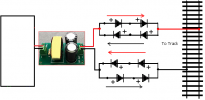
Diode String.png
 
Last edited:
Got it running!! I purchased the PWM converter like it was suggested. I Initially was going to install it inside the loco but it is a little bulky (not that it wouldn't fit) but I decided to install it between my PWM power source and my speed controller (one less thing to wire up inside the loco). My power source puts out 24v so I kept the speed controller set to 80% power. Installed the Piko Rc unit in a "direct" configuration as opposed to the "parallel" configuration i had before which used the original analog board in the loco. The boards were made the exact same size with matching mounting holes, so it fit great. I put the loco on the tracks for a test run, ran it for 20 minutes or so. Ran it back and forth slow and fast with no over heating, no smoke, it worked great. Thanks for all the help!
 
Back
Top