P A D
Registered
Thanks Jon,
I hope I can continue to gast your flabber as the thread continues.
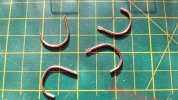
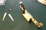
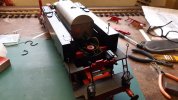
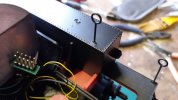
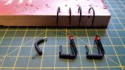
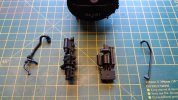
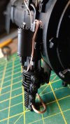
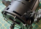
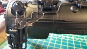
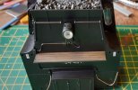
So, using the shanks of a grinding burr to get a consistent bend, the the wire is looped in between the sand pipes, to be located on a strip of plasticard glued to the underside of the sand gun body.
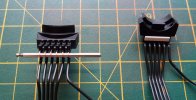
The wires are then adjusted and glued to the plastic strip.
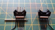
And then trimmed with side cutters.
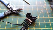
One sided done.
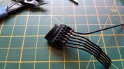
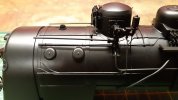
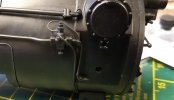
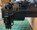
To complete the modifications to the sand dome, the missing grab rails were added using 0.6mm copper wire. The top edge of the side pieces needed filing to clear the excess grab rail wire inside the dome, otherwise it won't locate properly.
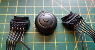
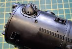
And with the three parts located on the boiler. They are not glued yet, as other pipes need replacing first and I will need to remove the sand pipes to do that.
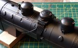
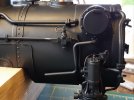
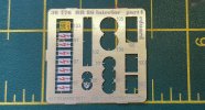
In preparation for refitting, I added some details to the plastic pipe work. First the valve behind the preheater on the right hand side had the hand wheel at the bottom replaced with an etched brass one I had in the spares box.
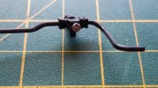
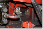
And I added the missing operating lever and condensate drain pipe to the whistle valve.
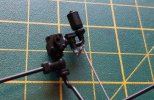
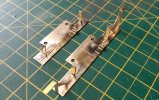
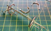
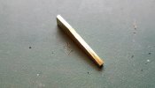
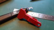
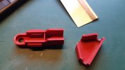
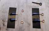
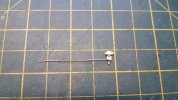
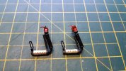
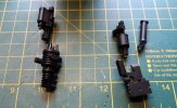
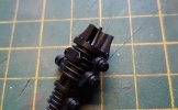
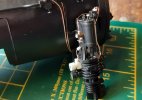
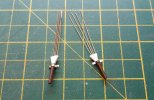
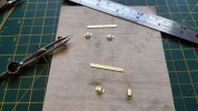
The too large gap between the top flanges on the steam heating coupling offended my sensibilities, so I sawed through the gap, filed off the excess, drilled both part and added a length of 0.8mm copper wire to reinforce the joint before re glueing together. Here are the parts with the pin glued in "pipe" ready for trimming.
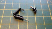
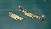
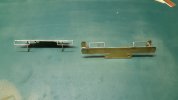
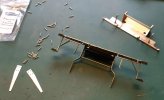
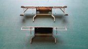
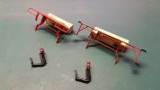
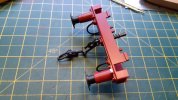
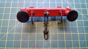
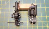
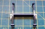
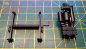
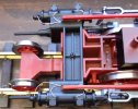
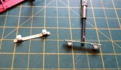
I then went off on a tangent and made a start on the missing under buffer details. First I made some base plates on which to fix the details, which will be located under the buffer beams via the bufferbeam fixing screws. This will allow easy removal should I ever need to run the loco on tight radius curves using the Piko tension lock coupling. The rear plate on the left, has the mounting for the steam heating pipe and the stowage brackets for the brake pipes. The front one has the same, plus the foot step brackets. Back in the comfort zone with these parts which are all fixed with 145 degree solder.
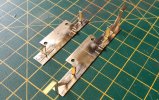
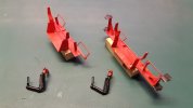
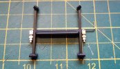
Here's the front plate after adding the footsteps, which again, came from the spares box.
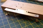
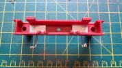
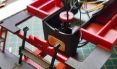
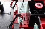
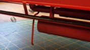
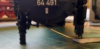
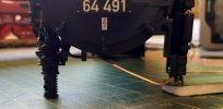
Here's a view from the underside showing how the steam heating coupling is mounted. It's a firm push fit in the bracket for now, but ultimately, it will be super glued. I daren't go near it with the hot stick, lest I melt the plastic parts!
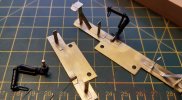
And with both couplings inserted.
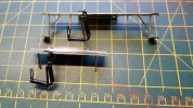
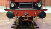
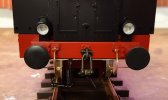
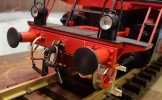
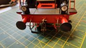
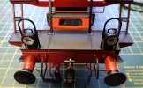
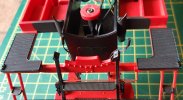
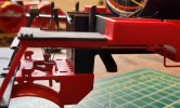
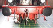
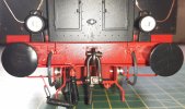
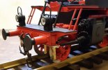
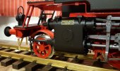
There are still some grab rails to be added, but here are the plates test fitted.
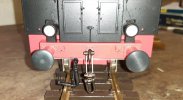
I will file back the front edges on the plates to disguise them, but they will also be less noticeable after painting.
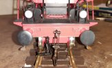
Some adjustment of the base plate will be necessary to get the steps to align correctly, but so far, I'm pleased with the result.
Cheers,
Peter
I hope I can continue to gast your flabber as the thread continues.
So, using the shanks of a grinding burr to get a consistent bend, the the wire is looped in between the sand pipes, to be located on a strip of plasticard glued to the underside of the sand gun body.

The wires are then adjusted and glued to the plastic strip.

And then trimmed with side cutters.

One sided done.

To complete the modifications to the sand dome, the missing grab rails were added using 0.6mm copper wire. The top edge of the side pieces needed filing to clear the excess grab rail wire inside the dome, otherwise it won't locate properly.

And with the three parts located on the boiler. They are not glued yet, as other pipes need replacing first and I will need to remove the sand pipes to do that.

In preparation for refitting, I added some details to the plastic pipe work. First the valve behind the preheater on the right hand side had the hand wheel at the bottom replaced with an etched brass one I had in the spares box.

And I added the missing operating lever and condensate drain pipe to the whistle valve.

The too large gap between the top flanges on the steam heating coupling offended my sensibilities, so I sawed through the gap, filed off the excess, drilled both part and added a length of 0.8mm copper wire to reinforce the joint before re glueing together. Here are the parts with the pin glued in "pipe" ready for trimming.

I then went off on a tangent and made a start on the missing under buffer details. First I made some base plates on which to fix the details, which will be located under the buffer beams via the bufferbeam fixing screws. This will allow easy removal should I ever need to run the loco on tight radius curves using the Piko tension lock coupling. The rear plate on the left, has the mounting for the steam heating pipe and the stowage brackets for the brake pipes. The front one has the same, plus the foot step brackets. Back in the comfort zone with these parts which are all fixed with 145 degree solder.

Here's the front plate after adding the footsteps, which again, came from the spares box.

Here's a view from the underside showing how the steam heating coupling is mounted. It's a firm push fit in the bracket for now, but ultimately, it will be super glued. I daren't go near it with the hot stick, lest I melt the plastic parts!

And with both couplings inserted.

There are still some grab rails to be added, but here are the plates test fitted.

I will file back the front edges on the plates to disguise them, but they will also be less noticeable after painting.

Some adjustment of the base plate will be necessary to get the steps to align correctly, but so far, I'm pleased with the result.


Cheers,
Peter

