Playmobil 27 mhz RC Electric Train (4010) Conversion

JimmyB

Now retired - trains and fishing
Country flag
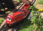
I have a working Playmobil RC train the red 27 mhz model, however I am now finding that due to the nature of my railway I have number of areas where the signal is lost, and those of you familiar with this loco will know it just stops. I am therefore looking to convert this to 2.4 ghz but with the original motor block, and add sound. Without a diagram I am have difficulties in stripping down the loco, and not wishing to damage the loco advice (or a diagram) would be appreciated, also what are my options for 4.8 volts for a Rx, ESC and sound card, for those unfamiliar with the loco a photo below in the hands of the grand-kids :)

Playmobil 4010.jpg
 
This link may help:

 
As there is plenty of space, I would probably go for a 6V NiMH battery pack. - I would be a little wary of a 7.4V Lithium pack, I think.
A MR001a(ab) receiver, the smaller Timpdon ESC, a MyLocoSound card, and a 'step-up' convertor (to give 12V) for the sound card.

PhilP
 
I dismantled one of these the other day, there easy to open up,
Just turn upside,
the bogies pop off with a bit of a tug, but be careful of the wiring on the powered on.
It’s a few screws, then can roof off, cab desk off and then body off.

the motor blocks are easy to open up, just 3 screws on the top, and a flat bladed screwdriver to open the clips

hope that makes sense.
I fitted a plug for a removable 3 s lipo, and a step down converter set to 6v on mine.
The sole reason was to allow me to use lipos and keep to one standard battery for all my locos

Dan
 
I can think of 3 options.

1) Remove the entire circuit board from the motor block, leaving only the motor and battery. Place the new 2.4 GHz receiver/ESC in the old motor block where the 27 MHZ circuit board was in the motor block. You might have a hard time finding one that fits.

2) Remove the entire circuit board from the motor block, leaving only the motor and battery. Place the 2.4 GHz receiver/ESC inside the loco body(in the compartment behind the seats... if you install the wall behind the seats backwards, then it can be opened again easily for access) then have the wires to the motor go down into the motor block in a similar fashion to the lighting wires, but connect directly to the motor. You also need to have the battery wires go up to the receiver/ESC in the loco body. You could have 2 wires from the batteries to the loco, then tap off of the power from the receiver/ESC for the lights, then have 2 wires go back down to the motor... so 4 wires total between motor block and loco.

3) Keep the original 27 MHz circuit board in the motor block, but bypass the receiver section of the circuit with a 2.4 GHz receiver in the loco body. This way I guess you would use the original ESC and H-bridge, but you would need to know the playmobil motor block circuit board well enough to know where the receiver section of the circuit ends. You could of course experiment to find where to connect the 2.4 GHz receiver to bypass the 27 MHz receiver.

Note: The link which Gordon supplied involves a 27 MHz RC car system. There are 2.4 GHz playmobil RC car systems, but I doubt they would be ideal for this situation as the playmobil 2.4 GHz controllers do not seem as suitable for trains.

I wonder if the circuitry from the playmobil 5258 could somehow be repurposed. I'm not sure how it could because the 5258 uses two motors instead of 1. But if it could be repurposed, then maybe you'd have directional lighting, sounds, and unfortunately the same lack of smooth speed control.
 
Last edited:
I wonder if the circuitry from the playmobil 5258 could somehow be repurposed. I'm not sure how it could because the 5258 uses two motors instead of 1. But if it could be repurposed, then maybe you'd have directional lighting, sounds, and unfortunately the same lack of smooth speed control.
If the 4010 were fitted with a second power bogie, would that work?
 
The 2-motor, 1-motor, thing is a bit of a red-herring..
The fact is, it is not a particularly good RC controller

Jimmy,
Do you have a, standard, battery you are trying to stick to across your loco's?

Is the question more about where to put the technology, rather than what technology to use?

PhilP
 
This link may help:

Not sure how practical this is for my situation.
As there is plenty of space, I would probably go for a 6V NiMH battery pack. - I would be a little wary of a 7.4V Lithium pack, I think.
A MR001a(ab) receiver, the smaller Timpdon ESC, a MyLocoSound card, and a 'step-up' convertor (to give 12V) for the sound card.

PhilP
Phil worth thinking about, though was considering keeping the original battery set up.

I dismantled one of these the other day, there easy to open up,
Just turn upside,
the bogies pop off with a bit of a tug, but be careful of the wiring on the powered on.
It’s a few screws, then can roof off, cab desk off and then body off.

the motor blocks are easy to open up, just 3 screws on the top, and a flat bladed screwdriver to open the clips

hope that makes sense.
I fitted a plug for a removable 3 s lipo, and a step down converter set to 6v on mine.
The sole reason was to allow me to use lipos and keep to one standard battery for all my locos

Dan
Dan thanks for the tips, my other battery set ups are lipo 3s, so keeping uniformity would be good.

I can think of 3 options.

1) Remove the entire circuit board from the motor block, leaving only the motor and battery. Place the new 2.4 GHz receiver/ESC in the old motor block where the 27 MHZ circuit board was in the motor block. You might have a hard time finding one that fits.

2) Remove the entire circuit board from the motor block, leaving only the motor and battery. Place the 2.4 GHz receiver/ESC inside the loco body(in the compartment behind the seats... if you install the wall behind the seats backwards, then it can be opened again easily for access) then have the wires to the motor go down into the motor block in a similar fashion to the lighting wires, but connect directly to the motor. You also need to have the battery wires go up to the receiver/ESC in the loco body. You could have 2 wires from the batteries to the loco, then tap off of the power from the receiver/ESC for the lights, then have 2 wires go back down to the motor... so 4 wires total between motor block and loco.

3) Keep the original 27 MHz circuit board in the motor block, but bypass the receiver section of the circuit with a 2.4 GHz receiver in the loco body. This way I guess you would use the original ESC and H-bridge, but you would need to know the playmobil motor block circuit board well enough to know where the receiver section of the circuit ends. You could of course experiment to find where to connect the 2.4 GHz receiver to bypass the 27 MHz receiver.

Note: The link which Gordon supplied involves a 27 MHz RC car system. There are 2.4 GHz playmobil RC car systems, but I doubt they would be ideal for this situation as the playmobil 2.4 GHz controllers do not seem as suitable for trains.

I wonder if the circuitry from the playmobil 5258 could somehow be repurposed. I'm not sure how it could because the 5258 uses two motors instead of 1. But if it could be repurposed, then maybe you'd have directional lighting, sounds, and unfortunately the same lack of smooth speed control.
Point 2 seems to be favourable.

Many thanks, I will consider my options.
 
The 2-motor, 1-motor, thing is a bit of a red-herring..
The fact is, it is not a particularly good RC controller

Jimmy,
Do you have a, standard, battery you are trying to stick to across your loco's?

Is the question more about where to put the technology, rather than what technology to use?

PhilP
Phil posts must have crossed, just considering my options, including keeping the original battery set up, or as mentioned going to lipo 3s.
 
If the 4010 were fitted with a second power bogie, would that work?
That's something I hadn't thought of. Good idea. Maybe it would work. But you'd have to figure out if the battery situation would be different. I'm not sure what the power specs of the circuitry and little motors in the 5258 are vs. the 27 MHz motorblock stuff. The 5258 seems to have more batteries than than the 27 MHz PM trains, so I'm not sure how well it would work with a direct swap out of the circuits. If someone has an open 5258, they could probably test how much voltage goes to the little motors at full speed and also test if the 5258 circuitry works with only 4 batteries to determine if they could use the same circuitry on the larger 27 MHz motorblock motors with the 27mhz. If the motors are comparable and if the 5258 circuit board still needs 6 batteries, perhaps the 2 battery holders in the 2 powered motor blocks could hold 3 batteries with a jumper cell in the 4th battery cell locations. Then the power from both battery holders could meet in the loco to connect to the 5258 circuit boards as normal
 
Been a while since I pulled one of these apart to use the cabs in a Railcar. But I was surprised how easy it was all easy access screws, but the chassis were a bit of a brain tease till I just shoved them out. As for the lights, I think that a new RC system would need a major rewire of them but not too difficult a job though some resister s may be needed if the voltage revised.
 
It pulls okay, its only the Grandkids using it, it the blind spots with the RC that is the issue, hence the upgrade to 2.4 ghz :)
I assume that you will be Deltang in it Jimmy? I reckon the small RX45 should be fine as I have used 2 of them in my Pway Car conversions using 4x NiMh Batteries in each one just fine. No high speed exploits but I would imagine that the PM Loco will perform pretty much the same as with the PM RC.
 
I assume that you will be Deltang in it Jimmy? I reckon the small RX45 should be fine as I have used 2 of them in my Pway Car conversions using 4x NiMh Batteries in each one just fine. No high speed exploits but I would imagine that the PM Loco will perform pretty much the same as with the PM RC.
Jon, very possibly, still considering using the 4 X NiMh fitted. All depends on what I find when I open it up. My other alternative would be the lipo 3S to keep it in line with my other RC locos, and a voltage reduction for the ECS/motor, I just need to understand how complicated each option is.
 
Jon, very possibly, still considering using the 4 X NiMh fitted. All depends on what I find when I open it up. My other alternative would be the lipo 3S to keep it in line with my other RC locos, and a voltage reduction for the ECS/motor, I just need to understand how complicated each option is.
Certainly my use of RX45 was easy peasy just using the wires on the board. I guess you could lash up a test rig using choc blocks and the existing wires cut to fit to see how it pans out prior to buying and more mods to use Lipo.
 
Many thanks so far for the advice, I now have the loco stripped down and can see what I am dealing with, and it would seem I have two main choices, and a hybrid choice (3):
  1. Just replace the existing circuit board with a suitable 2.4 Ghz Rx and ESU, something like the Deltang Rx 45, as suggested by Jon, a swap in and out which would be quite simple, keeping the original batteries.
  2. Move the electronics to the main body, power by LiPo (3S), MLS, and larger Rx and ESU e.g. Deltang Rx 65, with a step down converter (thanks Dan for the idea) for the motor.
  3. Keep the original batteries, move the electronics to the main body, use Deltang Rx 45 with a step up converter for the the MLS (thanks Phil for the idea)
It is now up to me to investigate the availability of the parts and feasibility of the actions :)
Not sure about the availability of RX65, last time I ordered some Deltang kit I wanted 2 65’s and he would only let me have one as the supply had apparently dried up. I heard a rumour that he was going to do some of his own variant but not sure how that has panned out as now that Fosworks have a selecta controller I think I will be sticking with them. My Deltang Selecta has 5 of the 10 options used so I have some spares if I do any more Deltang Locs. No doubt you will update us when you speak to whoever supplies your Deltang. But for my money the RX45 ought to be plenty man enough for what you want to do.
 
After considering my options, I have decided that I would like sound, so option (1) above is out, as I already have the NiMh batteries and a spare set, I have also decided that I will keep the original battery power. so obviously this means option (3) above is the way I am going to go.
My original concept here was to use the Deltang Rx 45, however PhilP PhilP suggested the MR001a(ab) receiver, the smaller Timpdon ESC, PhilP, please can you advise why this choice so I can understand the options and make my final choice.
 
My original concept here was to use the Deltang Rx 45, however PhilP PhilP PhilP PhilP suggested the MR001a(ab) receiver, the smaller Timpdon ESC, PhilP, please can you advise why this choice so I can understand the options and make my final choice.
The Rx45 is a 3-6V 500mA device.
I think you would exceed this limit if you were to stall the loco. - I believe you have both R1 and grades on your line?
It is also a tiny device, so you would probably have to decide what you wanted before ordering, so that it could be supplied pre-wired?

If you want sound, you are going to need a higher supply voltage for the sound card, so you would be fitting within the body, and space should not be at a premium.
The MR001a has pins for connection, giving you flexibility to experiment, without resorting to the soldering iron.
The ESC would give you the flexibility to swap to a bigger battery, if this proved necessary. - Tight curves, grades, a larger loco, and sound. All will add to the current draw, reducing your running time.

PhilP
 
Back
Top