Point and Signal Rodding

And when junctions were reduced in size or complexity the old signal box would stay with the number of in use levers reduced.

I'm by experience a power person but after spending time on multi discipline projects and then managing signalling upgrade and renewal projects one tends to pick up all sorts of useless information.
If anyone tries to tell you signalling is a black art its gollywoggle, signalling is like a flow chart but with lots of different combinations of scena
Indeed they would, I think this list of colours would help understanding a little.

Westinghouse Brake & Saxby Signal Co. Ltd. Lever Colours

Lever Colours. Controlled Device. Signal box.
RED, STOP SIGNAL, ANY. BLACK
POINTS, ANY. WHITE
SPARE, ANY.
YELLOW, DISTANT

Copied from a webb search not very well I fear! Oh just clicked on the link and it is much more comprehensive to the above list though this will work for most of us mere mortals.
 
And when junctions were reduced in size or complexity the old signal box would stay with the number of in use levers reduced.

I'm by experience a power person but after spending time on multi discipline projects and then managing signalling upgrade and renewal projects one tends to pick up all sorts of useless information.
If anyone tries to tell you signalling is a black art its gollywoggle, signalling is like a flow chart but with lots of different combinations of scena
Indeed they would, I think this list of colours would help understanding a little.


Westinghouse Brake & Saxby Signal Co. Ltd. Lever Colours​


Lever Colours. Controlled Device. Signal box.
RED, STOP SIGNAL, ANY. BLACK
POINTS, ANY. WHITE
SPARE, ANY.
YELLOW, DISTANT

Copied from a webb search not very well I fear!
 
There's an 00 model railway near here with the trains battery powered and radio controlled. All drivers obey the signals which are part of the fully mechanically interlocked system.
Details may be had by searching the internet for Shuttlewood Clarke Foundation Model Railway
 
Last edited:
There's an 00 model railway near here with the trains battery powered and radio controlled. All drivers obey the signals which are part of the fully mechanically interlocked system.
Details may be had by searching the internet for Shuttlewood Clarke Foundation Model Railway
My previous layout had a fully electrically interlocked panel, similar to a 1960's ish electric signal box with mini levers represented by toggle switches, with a signalling panel to identify the point and signal numbers.
Train operation was by DCC so if someone spaded a signal the whole layout stopped causing embarrassment.

Point drive was via a crank above the board mirrored underneath on which the point motor.

David
 
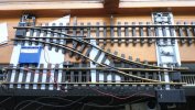
If nothing else I have learnt something about point control this weekend :) it sort of works, I know the point motor does not go where I have it that was just to see what happens when it trying to move all the links. It can move two sets of points and the links if you leave the joints free enough., but doing that allows backlash in the linkage so unless there was something like an over center spring at the points end then a Loco could move the points and cause problems. If I tighten things up enough to remove the backlash then it can only move one set of points and rods.

The alternative then is to improve all the pivots with bushes etc so the joints can be tighter to remove the backlash, or just use one motor per set of points / rods . The links on the Right were more complicated than they need be, that's so one motor would move the two sets of points from mainlines to crossover by moving both rods (upper right) in the same direction If two motors then that could be simplified.

Waiting now for the 2mm Brass rods to come so it can then be set up on the actual track outside to see if it would work in the real G Scale world.

My signals I know now will get Levers probably to operate them now :)

points4.jpg
 
If nothing else I have learnt something about point control this weekend :) it sort of works, I know the point motor does not go where I have it that was just to see what happens when it trying to move all the links. It can move two sets of points and the links if you leave the joints free enough., but doing that allows backlash in the linkage so unless there was something like an over center spring at the points end then a Loco could move the points and cause problems. If I tighten things up enough to remove the backlash then it can only move one set of points and rods.

The alternative then is to improve all the pivots with bushes etc so the joints can be tighter to remove the backlash, or just use one motor per set of points / rods . The links on the Right were more complicated than they need be, that's so one motor would move the two sets of points from mainlines to crossover by moving both rods (upper right) in the same direction If two motors then that could be simplified.

Waiting now for the 2mm Brass rods to come so it can then be set up on the actual track outside to see if it would work in the real G Scale world.

My signals I know now will get Levers probably to operate them now :)

View attachment 283710
You may find that some additional restriction places between the points will make things a little firmer. In the pic above you have just two.
 
Out of interest, is the Signalling Schools old layout still on view at the York railway museum?
It was out the back in one of the workshop areas when I saw it in 2015. Fantastic place when you peer into all the nooks and crannies, more to it than just the oft seen main hall.
 
Out of interest, is the Signalling Schools old layout still on view at the York railway museum?
Yes is still present or was when I last visited back in 2019. They have demo operating days I think once a month.
 
Does anyone know if the Swindon Panel Society completed the Signalling Centre at Didcot?

PhilP
 
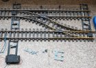
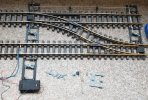
Think I have decided one LGB motor can not operate two sets of points and the rodding to make them switch in the right direction as a pair together, I have now tried 6 permutations of connecting it all up and this one worked the best moved the first set of points all the rodding right up to the point you connect the second set of points then it only half switches :( so it would derail a lot.
One set of rods and one set of points work great, and yes the rods on the left look more complicated than need be, but that was to get both sets to pull and push from the straight on positions to the cross over position.

It would work with a stronger motor or hand levers . So it's two motors on this bit I think to be able to control the crossover with the Navigator. But I can hide them in the Signal box :)

point2.jpg

points1.jpg
 
You can vary the length of the arms..
Either to increase travel, or to get mechanical advantage.

I would mount the motor to move the rodding parallel to the rails.
Then I would use one crank for each point.. By putting a joggle in the rodding, you can get clearance for one of the rods to the tie-bar to cross the main-run.
Less slack and loss in the system.

PhilP
I think you have nailed it Phil, certainly there appears to be a lit of places where tork can be lost.
 
The problem is its 10mm movement in at the Motor arm and 10mm out needed to move the points, so not sure how I can achieve any mechanical advantage ? The above pics probably aren't the best setup I had, but it was the best I got working outside, think I got bored and cold trying to get it working , so played on the office floor with the points until I gave up :)

I can turn the Motor 90 deg but it has to be where it is if I am hiding it in the base of the signal box :)
I am assuming you were short of movement, at the second point?

If you only have two cranks, then there is less 'slop' to take up.. If you make the output arm of the second crank a little longer (so the point the rodding comes of is further from the pivot, then you will get a longer travel. - Like moving out one hole, on a servo horn.
That extra travel, can make-up for the losses through the system.

PhilP.
 
It hasnt been short of movement it was just the resistance opf the second points, they push half way and the motor stalls then, if you move the points by hand a little it then pushes them all the way
 
Gotcha!

Is it a new motor? - Have you tried a different one?

I still think with one straight run, and one crank per point, you might gain enough?

Is there a problem with the second point?
 
Actually I have two new motors and one second hand that looks new, not actually looked which I used but will try swapping the motor this weekend :) Don't think there is a problem with the Second set of points , but out in the Garden is not the same as a flat office floor :) I joined it all back up outside tonight so trains can run again this weekend so I will play with the various cranks etc again if the sun shines this weekend :)
 
I would use offset cranks I.e. one arm longer than the other, and add omega loops. This should take up any short fall.
 
Only just seen this. I use only rodding for points -no motors. The rodding is 1.6mm welding rod, with lengths joined using the little 2-screw blocks from the small 'chocolate block' electrical connectors, and bell cranks cut from brass sheet. It all works well, but needs oiling regularly. The longest run is about five metres. The rods rust eventually, but it is easy to swap in a new one.
 
Back
Top