Possible motor problem with Bachmann Lyn

Hi Greg
I've tried increasing the number of li-ion cells from three to four, thereby increasing the nominal voltage of the pack from 11.1v to 14.8v and it made negligible difference - the most noticeable being that the motor block was tangibly warmer, nay hotter, after I had tried testing it.

I agree that my use of rotational inertia is probably a red herring, but that's because I'm not a physicist and so was trying to find some mathematical means of explaining what I was experiencing.

To help inform my understanding, I asked for clarification on an Engineering forum. To be honest, other than a gut feeling, I had no real certainty that the contributors would support or confound my implicit theory. The resultant response seems to suggest that the torque (Mw) required to turn the worm is directly proportional to the radius of the worm Rw


This is persuasive enough for me to continue with my experiments. As indicated above, the teeth on the new gears are very small and so it's difficult to get them to mesh reliably - and even when/if I do I think they will probably wear quickly given the loads I'll be placing on them, I've sent off for larger modulus gears and so will have to wait for them to arrive before I can redesign the gearbox. Life would have been so much easier if I could have found smaller worms which mesh directly with the original worm wheels.

Given that I have three of these mechanisms, I'm determined to find a way to get them all working.

Rik
Rik, the mechanical and mathematical argument are just what I was trying to explain, more eloquently, and with all the detailed information, I think this should end the discussion, so we can get back to trains.
 
OK - maybe some more red herrings, but firstly I only have a degree-equivalent professional qualification in a subject absolutely unrelated to what we're talking about here.

Probably the more relative experience is that I have played with trains for most of my 69 years, but only had electric trains since I was about 9 or 10.

I'm not in a position to challenge any of the scientific principles, it's just that I'm not sure that I can see them applying absolutely in our model world where so much of what we're talking about - electric motor, gears etc is, in scale terms, generally over engineered.

So, I'm probably repeating myself here, and being boring but:

  • The original large brass worms are, in my simplistic mind, unlikely to generate enough of a flywheel motion to achieve any benefit - maybe a Bachmann failed experiment.
  • The drive ratio at 35:1 shouldn't be too tall, but may be if the driving wheels are approaching 40 mm diameter. The 40:1 ratio with Greg's re-built gearbox should be better (purely in ratio terms)
  • I don't think a two-stage gearbox (as re-worked by Bachmann) eases the load on the motor in any way - my understanding is that it relives stress on the gear train.
  • A flywheel drive will be of little benefit when using battery power
All this still points me to the motor - but Rik has used a variety of motors, which is where it gets very puzzling.

Now, I could be shot down for this, but I seem to recall that using a mutli-pole motor i.e. a 5-pole or 7-pole will only deliver smoother starting a bit more bottom end grunt (very low) and doesn't deliver more power.

In some of Bachmann's other models, they use (I think Mabuchi motors) that have a low voltage draw, and are pretty lively (I'm thinking of the ones I have experience of such as the Mining Mogul, the Connie, and the 45 tonner) so, I'm still thinking that the answer could be with the motor.

Which leaves me pondering a bit, because as Greg found, someone had the same idea, and swapped a Buhler motor, which is normally considered to be quite powerful, although not always.

I still think the motor has got to be the answer, with a 40:1 gear ratio, and again based on experience and failure, a two stage gearbox would be preferable - but how that can be achieved .................... :think:

When I had got through three gearbox / motor combinations on the Yeti, I installed one of these using the 33:1 ratio with 28mm diameter driving wheels. Motor & Gearboxes — MSC Models

My 2-6-2 which uses 44mm driving wheels, has an ABC 50:1 gearbox, which makes it pretty slow and steady, and which hurts the bank balance a bit more :oops::oops::oops:
 
Last edited:
Right, notice this sentence from your mechanical forum:

Now the force that dominates the torque on the worm gear is transverse to the plane of the spur gear.

Like I said, most of the energy is used in converting the planes of the force, the 90 degree shift from the axis of the motor to the axis of the axle.

Anyway, it also mentions frictional losses, which are not insignificant.

Anyway, at this point experimentation is your friend.

Referring to the voltage experiment, thank you, so we can infer that the motor did indeed draw more current. Even though the extra heat probably makes it unacceptable, were you able to test if pulling power increased.

I'm continuing to think the only solution is a different motor, or perhaps gearing way down, but now the worm gears may get very large, and your enemy, friction may come more into play.

At the risk of asking stupid questions, are you getting any significant wheelslip? (Just wondering if any other solutions have been missed.)

Greg
 
I am happy to continue with my worm gear experiments - I am 90% certain this is the cause - it is demanding too much of the motor. I have eliminated weak motors as the cause.

No wheel-slip whatsoever - just a loco with no power. Performs, dare I say it, like a live steamer.

Rik
 
As a means to clarify one the key points in this topic that seems to be a vexed question may I add this explanation in a blessed light hearted mannnner -


Sit back enjoy and have mind defuddled. Those intenet algorithms seem to work in mysterious ways. Max

Which naturally leaves only one question to ask
 
Last edited:
Reading through this, and not understanding much of it, so this may have come up...but wouldn't the actual physical weight of a large worm, or 2, cause issues? It is a large lump of brass sitting on the end of the shaft
 
In theory yes, it should increas bearing wear, as nothing is "perfectly" balanced, but what increase? Is it significant?

It's all a measure of degrees. Notice the wide use of flywheels in model trains has not abated but increased.

In this case particularly, the second version of the drive train has had a flywheel added, significantly more weight and more inertia than the worm.

Greg
 
Not sure about flywheels?

All this talk, about torque, is making my head spin! o_O
 
It only took me three months .........


Rik
Well done Rik the lococlooks good.

A suggestion for the other diesel motor block left over, what about a small industrial side rod diesel similar to the ones used on Aust sugar cane lines.

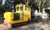
This is "Valdora" from the Australian Sugar Cane Railway" a local preservation society.
Valdora.jpg

There was an article in the old garden railways magazine where a person put one of them under a HLW Mack to make an industrial switcher.
Just an idea to kick around.
 
I see a new motor has been fitted also. I still believe the old motor just did not generate enough power, since the gearing is the same.
As you know, we differ on this. I agree that the gear ratio is the same, but the amount of effort needed to transfer the motion from the motor shaft to the worm wheel is now considerably less with the smaller worms.

I now have sufficient parts to make another motor block. If I can transfer the worms to the old motor I'll know for sure that it's the worms and not the motor which caused the problem.

Rik
 
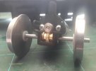
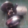
I appreciate the ship my be long gone on this one but I relate a recent tale regarding the assembly of 4 motor/gearbox units for a 16 mm scale deisel outline loco I am presently building. The gearbox housings are 3D printed (I do not have the spec of the material used). The gears are metal and I am told bought from a supplier as properly matched sets - a steel (presumed) worm driving and a brass pinion gear designed to fit on an 1/8th" dia axle. The ratio is 1:40, though 1:20 & 1:60 can be made available. The axle runs in brass bearings 1/8th" ID, 7 mm OD. See picture for the whole set up.The alignment of the bearing shells are determined by the total width of the bearings and gear on the axle matching that of the space between the casing's "horns".

I went through a total of 8 x 3D printed housings to make up the final 4 usable units required. This was done with the full, amiable and prompt assistance of their designer and maker. With two of the "failed" units it was impossible to align the axle to allow it's free running in the bearings and correct alignment of the gear sets. On 1 the worm gear was set so high in relation to the pinion they did not eve meet to mesh. The 4th and final housing delaminated when one of the bearings was inserted. I used a parallel jaw pair of pliers to insert the bearings so they did not go in skewed (not in the instructions). All the components from the failed units, apart from the gearbox casings naturally, were transferable to the "good" casings and proved to then work satisfactoraly. It follows the issues were either with the 3D printed casings or my skills in assembling. Remember these casings are all produce from the same file driving the same printer with the same feed stock material for each unit. Note - 2 of 4 initial gear box casings proved unusable and 2 of the subsequent 4 replacements supplied proved similarly deficient. So even with the experience of the initial 4 units and extra curricular measures employed to ensure successful assembly failure still resulted with the latter 2.

I had followed the instructions supplied to the letter and even went out and bought a 7 mm tapered hand reamer to ease the bearings' fitting to the housings. As well, I paid particular attention to the housings to remove any material that might stop the bearings seating properly or foul the pinion. I also checked for machining burrs on all the metal components and removed them with a fine cut miniature rat tail or flat file and polished all the end surfaces to give a tiny bit of extra play. The only "fix" was sorting through the casings supplied till I could find 4 that would work with the component sets supplied. I've done this stuff before with my own design slot car resin and etched metal chassis I used to manufacture. I have form here.

It struck me that the issue was achieving a consistent alignment, to the tolerances required, for the metal components supplied, from a 3D printed casing - using the method of 3D printing and material as supplied. A cordial conversation with the designer/supplier resulted in them suggesting/admitting that the material used was not one they used for other components in their range and that this might be the cause of the issues I experienced (apparently some faults were showing up already) - or as I would say the manufacturing process or material could not deliver either the dimensional stability required or the material cohesion required with the supplied components without some further preparation work outside the scope of the assembly instructions (7 mm reamer, etc'). And even then it might be impossible to produce a satisfactory working unit.

Something to keep in mind when all else fails with some 3D printed components, particularly in this application. It's still very early days, especially for those with "non industrial grade" printing equipment. Just my observations. Empirical I know but that's what I have concluded and the supplier was sympathetic with. Max

20210706_150233.jpg20210706_150349.jpg
 
Last edited:
Just out of curiosity, is this a filament printer or an SLA, or what type?

The resolution looks low. I have a friend that uses a very good SLA printer and even then accommodations/tweaks are necessary from the drawing to the final. He does achieve very consistent dimensions though.

So, just what kind of printer at what resolution please?

Greg

p.s. I really like those gears!
 
Back
Top