Some theory about reverse loops for DCC (as I understand it):
Nature of DCC power and signal
- There's no set +ve or -ve rail. Direction is determined relative to the facing of the engine.
- But, at any given point in time, one rail is
powered and the other is not powered +ve and the other -ve. These rails must not touch.
- The rails switch polarity up to 10,000 times per second.
- Passing a train over a separator could short the two half-rails together and cause them to touch. At the time the train crosses the joiner, both sides of the joiner must have consistent polarity.
Because the polarity switches frequently, the reverse loop module can get away with instantaneously flipping the
phase of a particular track. Worst case scenario is that the train decoder will read this as an unexpected signal flip and discard the packet as faulty. But control stations assume that
some packets will get lost, so losing one to the reverse loop module isn't a big deal.
The role of the sensor track and reverse loop is to normalise the phase (polarity) of the DCC power across the sensor track. When the sensor track is bridged (by the train running over it), the reverse loop module flips the phase of the controlled track to match the phase of the track at the sensor and the train continues none-the-wiser. But this leads to the most important rule -
only one sensor track can be bridged at a time. Note that bridged includes the loco, but can also include any other conducting material, such as cars with metal wheels.
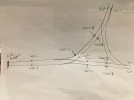
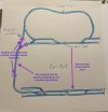
The nice thing about setting up the sensors as in Phil's first diagram (on both paths immediately after the turnout) is that it's basically impossible to accidentally bridge both sensors, as that would require two trains to be using the same turnout at the same time. In contrast, setting it up on both ends of one connecting track requires that any train can completely fit within that track.
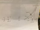
Phil - in your second diagram you have 3 sensor tracks. I assume that the sensor on one of the junctions is wired together with the sensor on the branch line. It won't matter which as long as the sensors are wired consistently (sensor-1, sensor-2 each on the same track). Then if a train crosses the other sensor, the "reversing section" phase is flipped and then flips back as the train exits the "reversing section".
Advantage of doing it like this: the reverse loop module only needs to provide power for a single train at a time (rather than all trains on the branch).
Disadvantage: you need to rigorously ensure that only one train is in that section. Specifically, you can't have one train exiting from one end while another enters from the other. (Technically you can, but only over the side of the junction whose sensors match.)
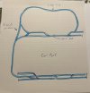
If my understanding is correct, you could use a single reversing section between two turning loops, putting the sensor sections on the branches of each turnout. At each end, one track pair is 1+2 and the other is 3+4. As long as no train is long enough to cross both turnouts simultaneously, the decision on which diverging track is 1+2 and 3+4 is arbitrary.
Another question: I note that the diagrams
always have Out+ between 1 & 3, and Out- between 2 & 4, with 1&2 paired on one sensor and 3&4 paired on the other. Is this required for correct operation? If so, I'm sort-of surprised they don't refer to the wires as P,P1,P2 (Out+, 1, 3) and N,N1,N2 (Out-, 2 and 4).
Likewise, I note that the fixed +/P rail always touches 1 & 4, while the fixed -/N rail always touches 2 & 3. Is this required?
Examples:
This will work:
P ---- 1 ---- (P) ---- 3 ---- N
N ---- 2 ---- (N) ---- 4 ---- P
Will this work?
P ---- 1 ---- (N) ---- 3 ---- N
N ---- 2 ---- (P) ---- 4 ---- P
What about this?
P ---- 1 ---- (P) ---- 4 ---- N
N ---- 2 ---- (N) ---- 3 ---- P
