Reversing loop modules - gory details

Sorry for the lack of clarity.

Consider the diagram in this post from the other thread (Phil's picture showing the main loop with a wye to the spur line, and purple overlay showing a "reversing loop" on the bottom of the wye and part of the spur line).

Now, rather than use the same booster for the main line and the spur line, consider that we use a different boosters, and we'll drive the "reversing loop" off the spur line booster. Does this cause any special considerations for the interface between the "reversing loop" and the connections to the main line?

Would the answer change if we drove the "reversing loop" off a third booster?

I'm assuming the answer is "no", but I'm not fully on board with any interfacing issues when trains cross between booster zones, so I wondered if that made for extra complexity for reversing loop modules.
I would certainly ensure that any reverce loop or wye is located completely an any one booster zone, or track section for that matter.
 
OK, I have the image:
436274_suggestion.jpeg


OK, so what you said is 2 different boosters and an autoreverser.

So as long as all the boosters are synchronized (normally this means running from the same command station), then nothing matters. The autoreverser will basically match the phase of the signal at the insulated point.

BUT

The normal proviso's are in force...
1. normally you want reversing loop length to be able to handle entire train (this diagram would need a short train.
2. if train can span reversing loop length, then no powered/lighted cars at the end of the train that can hit the insulators at the same time as the loco(s)
3. you still might have issues unless you have a smart autoreverser that can ignore small duration "shorts" from steel wheels... and this depends on the system. I cannot and won't speak to the sensor systems, they may be ok. The "shorting type" autoreversers I use have no problem.

I think you need to get a "feel" for how the units work, as opposed to coming up with dozens of different configurations and checking each one. i think by asking these questions you will get that knowledge and confidence.

I may seem resistant, and I will give you an example. In DCC, there is a register, CV29, where the individual bits control different functions. You really need to understand what a 1 or a 0 means in each bit location. Then you use binary math, or a "CV calculator" to get the resultant decimal number you enter.

I often come upon people who want to know the decimal value for this configuration, then minutes later, what about this configuration, etc. Often they refuse to learn how to do this or use an online calculator. When I tell them there are many many different possibilities, often they demand a sheet with all the possible values... I tell them that is theoretically 256 entries... the majority will still want a printed sheet of paper.

So, when I feel I am headed down this path of documenting every single permutation, I politely try to get them to get the fundamentals, and if they refuse, I find someone else with the time to go down the path of endless configurations.

Sorry for the long winded explanation. The nature of how an autoreverser senses when to flip polarity, and what NOT to do is much simpler than drawing many different configurations in my opinion.

Greg
 
1. normally you want reversing loop length to be able to handle entire train (this diagram would need a short train.
Greg, Wrong! The only reason I suggested this particular configuration is that it will work with any reasonable (and absurdly long) length train! Look at it again!
 
Last edited:
Conor I am glad I run on batteries and steam, none of this nonsense do me ;);):mask:
I'm glad that I'm totally analog! My (few) brain cells hurt when I look at all the details!. When I can't switch something off - or on - it'll be time for me to retire!
 
Yep Jimmy Mick, but this is becoming way more complicated than is needed in my opinion. But I see it as an adventure for some.
(Of course your comment is as helpful as a DCC guy commenting negatively on a battery thread, but its a forum. Will you be ok with me in the future coming on a battery thread where there are issues and thumping my chest about not having these issues because i'm DCC? I hope so)
 
Phil can you explain to me why this configuration allows a train longer than the reversing section over any other design?

What issues does it solve (better) than making the entire switchyard part of the reversing section? In relation to the length of the train as you state.

(Yes, not having the whole switchyard on the same reversing loop could be an advantage, especially to a cheaper reversing unit that cannot handle enough amperage).

If anything it will work worse on trains longer than the reversing section (when taking one direction, the other direction needs no reversing)

Greg
 
Yep Jimmy Mick, but this is becoming way more complicated than is needed in my opinion. But I see it as an adventure for some.
(Of course your comment is as helpful as a DCC guy commenting negatively on a battery thread, but its a forum. Will you be ok with me in the future coming on a battery thread where there are issues and thumping my chest about not having these issues because i'm DCC? I hope so)
Greg, the wink means it is light hearted, we all run our train our way, even within the same fraternity it is different, I use (and like) lithium batteries other don't, just as you are a big Zimo user and other don't. But in all honesty, most of this DCC stuff is way over my head, I read it (or at least some of it), but after nearly 3 years still have difficulty understanding it -fact :)
 
Phil can you explain to me why this configuration allows a train longer than the reversing section over any other design?
Greg, I was responding to your parenthetical comment that the configuration I showed "would need a short train". The insulated break near the yard could be moved all the way to the yard entrance if desired. This would accommodate any reasonable length train Oliver might want to run. (Or the insulating break could be eliminated entirely to make the entire yard reversing.) For that matter breaking the wye as I have shown allows the entire loop at the top of the sketch to be made the "reversing" segment instead if desired.
 
Good, so the configuration picture posted indeed probably limits you to a short train, as I said.

My advice is like yours, move insulators to the yard throat, or the whole yard.

I have a wye at my yard entrance and included it and the whole yard as one reversing section, but that section has an independent 8 amp capability, which will probably be enough. I do intend to have a number of locomotive consists in the yard, but most will be idling. We'll see if 8 amps is enough, if not, I can up it to 12 amps (or even 20) but it will be somewhat expensive (another Zimo MX10).

20181001_173021.jpg
 
Heck, my eyes glaze over somewhat reading NMRA S-9.1. But if I tell her that it works by flipping the polarity of a DC signal, and the decoders use the (variable) rate of flipping to read it as binary data, and anything that needs straight DC power can just rectify the flips away, she gets it, at least enough to understand what's going on.
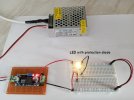
LED Circuit ON.jpg

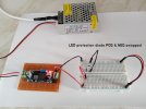
LED Circuit OFF.jpg

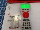
DCC LED ON Brown White.jpg

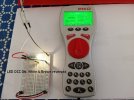
DCC LED ON White Brown.jpg

Arduino DCC Base Station.jpg

Notes Pages 1 & 2.JPG

Notes Pages 3 & 4.JPG

Notes Page 5.JPG

Billybull Shit 5.JPG
 
Was there a point to that long post?

Yes, put a full wave bridge on a bipolar square wave, and you get pretty good DC with a minimum of filtering.

If the wave was perfect, then there would be no filtering. Our waves have ringing, not flat tops, rise time, but still, very easy to filter, nothing like what you need to filter a sinusoidal wave to DC.

why can't you call AC bipolar DC with a rise and fall of a gaussian curve? Sure you can, if your reasoning is that you can rectify it.

Sure and you can call an sutomobile a box with wheels that turn.

Bipolar DC of course misses the Digital modulation aspect.

Call it bipolar DC but what happened to your ground reference? (think about it) Wait until your friend uses his DC meter to read his "bipolar DC".

Think about the ground reference issue in terms of defining the voltage, looking it as DC.

Live in any world you want, just try not to talk to an engineer or anyone with an advanced college degree in electrical engineering or a physicist.

I'm calling my power company and tell them I want gaussian curve bipolar DC served to my house. In face we will start a movement to eliminate AC altogether.

Greg
 
I'm steady, but, no, it was an argument about calling an AC signal Bipolar DC.... the reasoning used basically allows you to call any AC signal "bipolar dc"

Bipolar DC is already defined by professionals and educational institutions.


I've had this argument over and over, and calling it DC of any form is a disservice to people who will put their meter on DC to measure DCC... so it's not helping the vast majority of DCC users whose first question is "what is your DCC voltage" .... (most do not give too hoots of the mechanics of getting DC from DCC, since the decoder normally provides this).


This is what this is about in a nutshell. Please read the entire post, not just the lead-in.

I have several electrical and RF engineers working for me, and we design and build communications systems that use square waves that are modulated... no one ever calls it bipolar DC.

I thought we were entitled to have factual disagreements, as long as they stay factual and courteous?

Greg
 
Back
Top