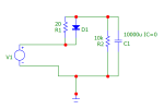
As a small update, I've been collecting electrical components to build the capacitor "circuit". Not a big project for the experts here, but I figured I'd share how I'm going to build it and hopefully not embarrass myself too much. I'll be traveling for work in the coming days so no time to test anything on track yet. The plan would be to connect the below to a track section that would become unpowered when a DPDT relay (LGB 12030) is switched by a reed switch (LGB 17100 Track Contact) as per the schematic in my first post. I'll start with 10k uF capacitance and work my way up to whatever works (per my research probably more like 30-40k).

I added the current limiting resistor R1 as suggested here and I included the 10k Ohm R2 to slowly drain the capacitor(s) when the system is turned off.
One thing I couldn't figure out is if there was a way to protect the capacitors from a voltage reversal in case I wanted to move a train backwards. Given that it is easy to do with my knob-turn throttle, I'm really worried it might happen. I'd be happy for any advice! Correct me if I'm wrong, but I think if I put a diode on the negative side of the capacitor, then I wouldn't get the capacitor to discharge into the unpowered track. I'm just having this thought - what if I put a diode in the power connection to this part of the track (via the DPDT), in other words, so that a train could only ever go forward in this section and if track power is reversed, this portion of track would become unpowered?
Also - the plus side of the capacitor (long leg) is to be connected to the plus side of the power supply/rails, right?
On the voltage dropping piece, I think I'll try it with two full wave diode bridges (per Greg's site) with 4 diodes in the path for 2.8V drop per segment. I've just set these up on a breadboard and will test and can easily add more depending on need. But it will take 3 isolated track sections which, as I've been warned, will take up a lot of space and the reality is I'll probably need more. All but one of my locos are LGB analog single motor models so I at least have the advantage that they don't need high voltage to run at a reasonable rate (at least that's what I'm telling myself until I find out otherwise) and so maybe I can get away with two steps.
