TBH I didn't think of it in that way, but its still part and parcel of enjoying your trains, and is obviously a hobby in its own right.Sorry to cause any disagreement, but as I state above "people may disagree with me, but that's their choice". To me, DCC as a "modelling activity" cannot be compared to the construction of say, a finescale locomotive or a super-detailed station building under the activity of "railway modelling". DCC is merely a potential way of making models move and I can do that with analogue DC just as easily!
Sorry but that is my view.
Dave
You are using an out of date browser. It may not display this or other websites correctly.
You should upgrade or use an alternative browser.
You should upgrade or use an alternative browser.
Where to put the breaks?
- Thread starter The mechanic
- Start date
JimmyB
Now retired - trains and fishing
Just remember how wide Railway modelling is from: scratch and kit building, layout building, electronics "fettling", battery conversions, timetable running, or even shelf queens, we all love different aspects, singularly or multiple, and to us it is our hobby, so each to their own 
Rhinochugger
Retired Oik
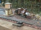
You can buy simple DPDT switchess that have rubber boots for external use. You can then fix them in a waterproof box and just house them in some suitable lineside structure. Mine sit under the water tower.Sorry to cause any disagreement, but as I state above "people may disagree with me, but that's their choice". To me, DCC as a "modelling activity" cannot be compared to the construction of say, a finescale locomotive or a super-detailed station building under the activity of "railway modelling". DCC is merely a potential way of making models move and I can do that with analogue DC just as easily!
Sorry but that is my view.
Dave
It may not be the most beautiful solution when photographed close up, but the switches have been outside in this situation on two railways over about 15 years, and i replaced the switches a few years ago when one failed.
Simple and effective - these switches control the isolation to my three loops in the station and wiring is just taken back to the nearest rail. I only isolate one side of the loop, as i run simple, very simple, DC

JimmyB
Now retired - trains and fishing
This is my solution to switches out side:

 tumble-down-falls.blogspot.com
Kippo Signal Box
In my engine siding I decided that the points (switches) control would be motorized via a local...
I have a similar set up. Use insulating rail joiners between the crossover and the switch ( point) on say the up line side. Remind yourself of which way both controlled need to be set so that the loco goes over and continues running. With one engine in steam it is no problem.Hello all,
The new layout is coming on well but.I have a bit of a conundrum.....
I have attached a rough schematic diagram that shows the track layout (both rails) of my main station. I use LGB standard trackwork. The station limits are joined by two loops that run around the edge of the garden. #1 is linked to #1 and #2 is linked to #2. I feed 12v-18v analogue DC at the ponts shown by the feed symbols.
Now, I know that the cross overs need isolating, but I am asking you kind people, where is the best place to put them in order to avoid additional switching and track power feeds?... I really want to reduce these to the absolute bare minimum thereby having the operation pretty "automatic" and "idiot-proof" (or should I say male Sixty-something-proof?) if at all possible?
Each loop will be operated on an independent "one engine in steam" principle.
I feed the layout via two hand held first-edition Train Engineers ( one per loop) that are commonly fed by a 24v/ 30amp stabilised power supply located indoors. Which is OK when the two loops are running independently, but at some point (no pun intended) I will need to run-round and/or shunt the two sidings. If I am using a common power supply for the TEs, there is short circuit potential at the crossovers where metal wheels can bridge isolating track joints? I am open to using diode-protected section breaks if this is feasible to avoid this scenario (however, my head cannot handle this sort of "electrickery")
I welcome your suggestions and opinions on this
Dave
