Did you check the red 8 switch DIP switch on the main board? This is the one that controls the pantographs. Check the brochure SoftwareTools linked for the correct switch positions. Someone might have turned all of them off thinking this was for selecting analog only or decoder DCC decoder equipped. That is what the gray 6 position switch dip is for. By the way, these 6 switches MUST be and remain in the OFF position if the loco has a decoder installed. Otherwise the decoder may emit its magic smoke.This engine doesn’t operate Pantographs on DC, something I will check.
You are using an out of date browser. It may not display this or other websites correctly.
You should upgrade or use an alternative browser.
You should upgrade or use an alternative browser.
Why so much electronics for a DC Locomotive?
- Thread starter Airbuspilot
- Start date
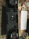
After checking the brochure myself it was not clear what was on and what was off for the 8 dip switches. The black in the brochure represents the position of the toggles as verified by the photo of the interface board in my loco. The toggles in your photo are correctly set for the "Standard-Position". The second pic is of the holes I drilled for the speaker. These were patterned after the holes in second newer MLGB Ge 4/4 III I have. If or when you add sound to your locos you will need to do something similar.
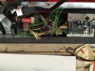


I just checked my XLS decoder equipped Ge 4/4 III on analog DC again. The front pantograph does go up and down as expected with the direction of travel. The rear pan on mine stays up just as it does when operated digitally. I don't know if this is normal for this vintage loco (MTS I, 14 speed step serial) or there is a problem with mine. I checked my much newer multi-protocol MLGB Ge 4/4 III (COOP) on analog DC and both pans go up and down as they should with the travel direction.This engine doesn’t operate Pantographs on DC, something I will check.
Last edited:
Did you try address 3 (the DCC decoder factory default address) just in case the address was mis-read for some reason?I could read its address as no 1 on the programming track
Edit added: you said the lights worked but the loco did not move on address 1. Did the lights respond to a change of direction?
Last edited:
Airbuspilot
Registered
Hi PhilDid you try address 3 (the DCC decoder factory default address) just in case the address was mis-read for some reason?
Edit added: you said the lights worked but the loco did not move on address 1. Did the lights respond to a change of direction?
I have not been able to work on the track for the last week but will go over n Monday with luck, I will look at your observations then.
I looked at the Massoth paperwork on the decoder you mentioned, for once it does seem to be well written and understandable. I hadn't thought about converting the loco just yet but it would seem to be a reasonable project. For my understanding does the new decoder replace all the electronics inside as a stand alone or do I need to combine the old and the new? First option would be reasonable second option possibly not so easy.
The Zimo MX32 needs to use address 2-10299, not 1 or 0.
The MX32 also needs to be programmed for proper speed steps to match what is in CV29 of the decoder. If 6 then you may have to use 28 speed steps for the 55020 decoder and if it is a LENZ decoder then 14 speed steps only.
Both Lenz and Massoth made the 55020 decoders. Lenz version is very restricted and does only 14 speed steps. Massoth version can do 28 speed steps, but not 128. Hence enter the Massoth 55021 decoder which was 14 or 28 in the beginning and later versions could do 128 steps.
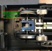
Actually, the Massoth XLS decoder interfaces to the loco's existing DCC interface board. This makes the installation MUCH MUCH MUCH easier than ripping out the existing interface board and trying to wire things directly. The Massoth number for the XLS sound decoder with LGB Ge 4/4 III sound project installed is 8230042. The decoder comes with the correct speaker. Any sound decoder could be used with the correct size speaker but you'll want to get the Massoth 6 conductor interface cable to make hook-up easy. The first two pictures below show my installation. I used one existing hole in the weight and drilled a second to mount the decoder on the weight.For my understanding does the new decoder replace all the electronics inside as a stand alone or do I need to combine the old and the new? First option would be reasonable second option possibly not so easy.
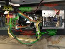
A second set of MOT+, MOT-, GL+, and GL- leads can be made up with these crimp-on plugs seen near the bottom of this page AllAboutLGB: LGB train Repair Parts The crimp-on plugs are also available here 60037 Power Pickup Plug, 10 pieces and here Kabelschuhe System LGB®, 10 Stück. I keep a stock of these with my spare parts just to have them handy.
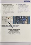
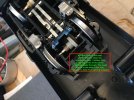
I also installed a Massoth eMotion Reed Switch Board when I put in the XLS decoder. It is designed for LGB motor blocks and is OEM for LGB locos that come with reed switches. These switches trigger the whistle when the loco passes over a track magnet. The next two pics are of the reed switch installation.
This is a good time to put in a Massoth eMotion Volume Control Board, No. 8242010 if you want manual volume control. I did not. I set the maximum sound volume to what I consider reasonable by decoder CV.
Last edited:
Airbuspilot
Registered
Thanks DanThe Zimo MX32 needs to use address 2-10299, not 1 or 0.
The MX32 also needs to be programmed for proper speed steps to match what is in CV29 of the decoder. If 6 then you may have to use 28 speed steps for the 55020 decoder and if it is a LENZ decoder then 14 speed steps only.
Both Lenz and Massoth made the 55020 decoders. Lenz version is very restricted and does only 14 speed steps. Massoth version can do 28 speed steps, but not 128. Hence enter the Massoth 55021 decoder which was 14 or 28 in the beginning and later versions could do 128 steps.
The loco was believed to be analogue but I discovered the decoders when I opened it up and they were identified via this forum. The address, presumably by the previous owner, was set at 1. Next opportunity I will change it and look at the speed steps.
Robin
Airbuspilot
Registered
Actually, the Massoth XLS decoder interfaces to the loco's existing DCC interface board. This makes the installation MUCH MUCH MUCH easier than ripping out the existing interface board and trying to wire things directly. The Massoth number for the XLS sound decoder with LGB Ge 4/4 III sound project installed is 8230042. The decoder comes with the correct speaker. Any sound decoder could be used with the correct size speaker but you'll want to get the Massoth 6 conductor interface cable to make hook-up easy. The first two pictures below show my installation. I used one existing hole in the weight and drilled a second to mount the decoder on the weight.
View attachment 294070
View attachment 294071
A second set of MOT+, MOT-, GL+, and GL- leads can be made up with these crimp-on plugs seen near the bottom of this page AllAboutLGB: LGB train Repair Parts The crimp-on plugs are also available here 60037 Power Pickup Plug, 10 pieces and here Kabelschuhe System LGB®, 10 Stück. I keep a stock of these with my spare parts just to have them handy.
I also installed a Massoth eMotion Reed Switch Board when I put in the XLS decoder. It is designed for LGB motor blocks and is OEM for LGB locos that come with reed switches. These switches trigger the whistle when the loco passes over a track magnet. The next two pics are of the reed switch installation.
View attachment 294072
View attachment 294073
This is a good time to put in a Massoth eMotion Volume Control Board, No. 8242010 if you want manual volume control. I did not. I set the maximum sound volume to what I consider reasonable by decoder CV.
Thanks for all this great info Phil. It doesn't look as difficult as I first thought, within my capabilities and definitely worth the effort. Things will slow down for a while, we only have two months of rain here and it's now, when it rains it tends to be horizontal and houses here tend to leak, not good for domestic bliss.
Probably next Monday for my next visit to the layout, I will look at all the suggestions above when I get there.
Regards
Robin
I tried to consolidate all I've discovered about the decoder installation in a new thread: Installing a Massoth eMotion XLS in an LGB Ge 4/4 IIIThanks for all this great info
I'm quite happy with mine now!
Hi again Robin,Gentlemen you are correct, it is DCC. I could read its address as no 1 on the programming track and various CV’s. CV 29 read 4, trying to run the engine on the main was unresponsive.
I changed CV 29 to 6 and the lights worked but still no movement on the main track.
The engine runs perfectly on DC so presumably I need to switch ON the DCC in some way?
I was reviewing some things on this thread and just thought of another issue you may be having. Mark may be able to help here too. Is it possible the two decoders have different DCC addresses? I know things can get garbled when there are two decoders on a programming track. Maybe one had its address changed so it could be modified without affecting the other decoder and someone forgot to change it back. Or maybe one decoder is locked and that is causing a problem.
This could explain why the loco works OK on analog but not on DCC. Both decoders are responding as expected to analog power but don't know what to do with DCC.
Glad I found this thread as I’m hoping to fit a decoder into an LGB 20420 MOB locomotive.
Does anyone know if the decoder can be programmed so that the pantographs can be switched on and off by pressing say F1 though the pantographs will only raise when the loco starts moving and automatically lower when it stops?
Does anyone know if the decoder can be programmed so that the pantographs can be switched on and off by pressing say F1 though the pantographs will only raise when the loco starts moving and automatically lower when it stops?
