Wiring LEDs for DCC....?

Thanks Alan - I thought that might be the case, but any idea actually WHY?

Jon.
Tiny current, tiny resistance. i am no electrician - it just works.
 
I take a passenger car for example, and cut 2 strips (each 1/2 the length of the car) of those "LED strips" and then run them in series, feed from a full wave bridge, perfect,

That is 1/2 the current if you ran them all in parallel. Each strip gets 12v that is the nominal requirement. Most of those 12v strips run pretty close to full brightness down to 9 volts, so putting 2 strips in series works for an 18v track voltage also.

My track voltage is 24 volts (Zimo lets you set it).

Greg
 
So, Greg, you CAN run these is series then....? I assume that to do this, you connect the +ve supply to the + terminal of the first strip, the -ve terminal of the first strip to the +ve of the second strip, then the -ve of the second strip back to the supply -ve.....?

OK, going back to one of the earlier questions about reversing polarity through an LED..... I'm part-way through dismantling the little railcar in question (the same one for which I asked the questions about USAT motor blocks in another thread), and the more I uncover the more puzzled I'm getting.
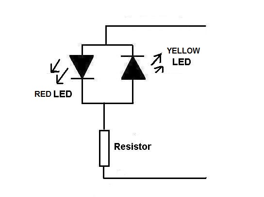
The vehicle is wired for analogue operation. At the front it has two yellowish LEDs for headlamps, and two more red LEDs at the other end for tail-lamps. As far as I can see, each LED has a limiting resistor fitted, but there is NO other protection for them such as inverse diodes, bridge rectification etc. When the vehicle is moving forwards, all the LEDs illuminate (head and tail lights). So far so good..... but when the vehicle is run in reverse, none of the LEDs light at all - which is as I'd expect, since they are getting the wrong polarity - BUT they don't burn out or seemingly suffer any kind of damage or ill effects. Turn the controller back to forwards voltage, and all the LEDs come on again just fine.
This is very much at odds with a lot of the posts above, by the answers given earlier the LEDs should all have burned out the first time the vehicle was ever run in reverse! Can anyone shed any light (pun!) on what is going on....?

Jon (Confused of North Essex).....
 
Is there any other circuitry in there Jon?
Like a regulator or a rectifier?
Normally.........
For the front and rear to operate independently or in tandem so, for instance, the front and rear came on in forward and the rear only in reverse. There would need to be a rectifier on the rear ones so that they light no matter what polarity (direction) is applied.
The front one would need a 'protecting' diode for the reverse direction to stop the led receiving voltage when in reverse.
Rectifiers can be very small indeed ... take the example of the little 16-19v E5.5 screw led bulbs that I use (they fit Pola exterior lights and some LGB fittings). They have a resistor and a rectifier in the remaining room in the screw base so possibly there is some circuitry hidden somewhere................

Anyhow I am off to have dinner at the top of The Hague Tower.....so will touch base later......
Chin chin
 
I don't think there is anything hidden, Mike - this model was built quite a few years ago, I think, and all the "electronics" are very basic - strips of good old Veroboard with simple discrete components on them - I've accessed the vero strip that carries the two LEDs for the red rear lamps, and it has nothing but the two LEDs (the old standard type bell-shaped mouldings with two wire legs, what LEDs always used to look like when we first got to know of them!) and two small resistors, one for each LED. This lighting board assembly is fed from direct DC track power, so will get reversed polarity when the controller is put into reverse. They light in forward polarity, they don't in reverse, but they don't burn out. Absolutely no sign of anything else wired in to the circuit, that I can see....

Jon, still rather puzzled.....
 
This lighting board assembly is fed from direct DC track power, so will get reversed polarity when the controller is put into reverse. They light in forward polarity, they don't in reverse, but they don't burn out. Absolutely no sign of anything else wired in to the circuit, that I can see....

Jon, still rather puzzled.....

Jon, apologies for causing confusion.
In general there is often no "right" answer but some methods suit some applications better than others.
If I understand correctly you'd like the four leds to light up as at present when going forward but change colour in reverse.
This could be achieved by adding four more, two red and two yellow adjacent to the existing but the other way round, or changing the LEDs to bi-colour ones. If going for the bi-colour option the resistor may need to change.
 

Attachments

  • 3A.jpg
    3A.jpg
    18.1 KB · Views: 4
Thanks Neil - in fact, I'm really not worried about the lights when running the vehicle in reverse - the only time it will do that is when moving about the yard, it's not a double-ended railbus and will normally be driven forward only - provided the lights are set right for that (which they are), that's all I'm concerned about.
My questions and puzzlement mostly come from previous posts in this thread - many people are of the opinion that reversed DC polarity will destroy an LED, and several solutions and methods of protection have been suggested - my confusion is that as currently wired, the LEDs in the railbus seem to survive reversed polarity just fine when the vehicle is backing up - they don't light, of course, but neither do they emit any magic smoke....
All this came about because I want to DCC chip it, and thus I was asking whether I can retain the same resistors that are presently installed for DC operation.
Given that I'm using an LS in the vehicle, I think my best plan is to simply wire the present lighting circuit straight to the light output socket of the LS, being very careful of the polarity of the function and ground connections of course, and then turn the lighting voltage down via CV to around 12 volts - that SHOULD simply make the lights work just as they presently do under DC (though with the bonus of controllability of course) and also remove any risk of reversed polarity.
Does that all make some sort of sense?

Jon.
 
Just back from the meal Jon, so a little reply.
Yep those are old LEDs and old circuitry...... no clever little micro components in that lot.
What you suggest makes sense to me ......... But still totally mystified as how the two LEDs are surviving the reverse polarity. When I have tried that to some ordinary bog standard LEDs, just out of devilment you understand, they would not light up again when the correct polarity was administered.
They were OK after up to about 6v or so reverse polarity but higher voltage and 'sploff'.
Perhaps they made them tougher back then........ Just like men...... Or some women...
 
Ahh, now if you ask an electrical engineer, he will tell you that you NEED to protect an LED from excessive reverse voltage, assuming the voltage is over 4 volts.

Many, many people do not add any protection and subject their LEDs to reverse voltage in excess of the manufacturer specs. I have RARELY seen a failure in this case, but it can happen.

Just my experience with LEDs.... now of course, running from a decoder never subjects the LED to reverse polarity.

On the LED strips for lighting, connect them to a full wave bridge... so on either DCC or DC, track voltage up to 24 volts, your two 12v strips in series will work fine.

Greg
 
Looking at the standard specs for a 5mm red led from Maplin I see the forward voltage is 2.5v at 30ma and the reverse voltage is 5v. Therefore if the resistor is sized to provide for the 2.5v volt drop at 30 ma over the LED in the forward direction it will be the same volt drop when the polarity is reversed and hence the 5v will not be exceeded. This is why LED's can be used on low voltage AC and I assume how they make the lights reverse on an analogue DC loco.
 
Interesting and very useful, Graham - I think you may have nailed it....

Jon.

At last my training as an electrical engineer has had some use, mind when I did my training LED's had not been invented :think: we had only just invented the transistor :rofl::rofl::rofl::rofl:
 
All this came about because I want to DCC chip it, and thus I was asking whether I can retain the same resistors that are presently installed for DC operation.


Jon.
I respectfully suggest double checking with your DCC chip instructions or supplier.
I fear it may not always be straightforward. I say this as, whilst I haven't done many DCC installations the last two used NCE D408SR decoders. The instructions in this case state different CV values for LEDs than for bulbs.
 
The difference in CV values are normally to use a different dimming "curve" for when the lights are dimmed... incandescents dim "quickly" with a little voltage reduction..... LEDs are current driven devices and will work over a wide range of voltages, so the "dimming curve" applied to LEDs must be different.

Greg
 
Back
Top