G Scale Tram Project

Interesting photo. It seems as if the tram on the right hand side is closer to the photographer, but is it?
 
Interesting photo. It seems as if the tram on the right hand side is closer to the photographer, but is it?
Jasper,

I hadn't noticed that, I thought both models were parallel to each other but wasn't sure so I took another photo of two different liveried trams side by side, these two were carefully lined up to be as parallel as possible.

Again the one on the left has the new truck.

David
 
First truck finished with the exception of the tray which I'll make and fit once its had a few test runs to check a few things.

MkII is under construction, the only real change from the original design is to tidy away cables and solder cable clips to the truck, basically a much tidier arrangement for the cabling.


David
David, I have read through this thread again, and I understand the side-frames etc came from KW, but I cannot see which motor unit you ended up with, the Applegate or the Fosworks.
 
The first tram has been fitted with Appletree traction motors, simply because I had the two motors on the bench.
The first open tram will be fitted with a pair of Fosworks traction motors because they are a smaller diameter and the open tram has a lower floor level.

I haven't yet worked out what the battery arrangement will be for the open tram.

One thing I have realised since fitting couplings to a tram and trailer, is that if the axle box springs are too light when coupling the tram has a tendency to lift the trailer enough that the couplings don't sit level until they've run over something less than smooth.
Tram is fitted with 0.5x4x6mm springs.
Trailer is fitted with 0.4x4x5mm springs.
That doesn't sound like much of a difference but it makes quite a bit of difference in running.

I have started drafting up a "how I did it" article for anyone who might want to do something similar to me, or use any part of what I've done.

David
:)
 
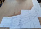
Well I finally pull the finger out and glued down the track template for the indoor tramway corner baseboard.
I obviously need to make 3 crossing units but the plan is to only use 1 switch blade for the whole track plan in the photo.

As the whole corner track plan needs to be scratch built, and because I might decide to infill the track to make a road way so that it looks like a tramway I won't be using any sleepers, they wouldn't serve any purpose once the roadway has been laid anyhow.

Unfortunately the original plan was to interlaced some plan track to build the track on this board so I don't have all the plain rail and chairs I'll need but at least I can now make a start, yippee.
 

Attachments

  • 20210814_154058.jpg
    20210814_154058.jpg
    344.1 KB · Views: 0
Well I finally pull the finger out and glued down the track template for the indoor tramway corner baseboard.
I obviously need to make 3 crossing units but the plan is to only use 1 switch blade for the whole track plan in the photo.

As the whole corner track plan needs to be scratch built, and because I might decide to infill the track to make a road way so that it looks like a tramway I won't be using any sleepers, they wouldn't serve any purpose once the roadway has been laid anyhow.

Unfortunately the original plan was to interlaced some plan track to build the track on this board so I don't have all the plain rail and chairs I'll need but at least I can now make a start, yippee.
Such a pity that small section brass U shape is so expensive, this is a dead ringer for some of that. Bit tricky to curve though, but annealing it would work.
 
Thankfully I have rollers which I normally use to roll 7mm scale boilers, that are perfectly capable of rolling code 200 rail, filing the rail for the crossings is a little different, the rail can be held in my bench vice rather than be clamped to a piece of scrap wood.
The biggest challenge I have is that I need the dinning table to lay out the template rather than laying thge turnout track plan out on the work bench, which is going to slow progress a wee bit because apparently the dinning table isn't there to only be another modelling work bench.
I use a cutting disk in the angle grinder for the flangeways in special work. Before I had that I used a broken hacksaw blade, but that is a lot harder!

Such a pity that small section brass U shape is so expensive, this is a dead ringer for some of that. Bit tricky to curve though, but annealing it would work.

It sucks you can't get proper girder rail in a profile useful for this scale. It would make trackwork so much easier. If you use normal profile rail to do the flangeways (like Sydney and probably some other systems did) it ends up eating up a frightening amount.
 
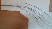
It's all very rough just now but it's a start, the baseboard unfortunately is in the vertical plane because my wife is off on Monday's and I keep being reminded the dining table isn't just another bench for me.

Wednesday will be spent cutting thin copperclad for the sleepers on to which I have decided to solder the rails instead of using chairs. Using copperclad will also allow me to solder scrap bits of material for the roadway surface to key on to.

It's a bit different working with code 200 rail as opposed to code 124 but we are slowly learning the best methods not to injure ourselves.

I knew the models would be bigger and the track would be a wider gauge, but it's only when one starts building something like this that you really come to appreciate the scale of the larger scale modelling.
This baseboard is big enough for me to build the corner section of my test track, just behind this baseboard is another baseboard of almost the same size and it has on it the complete balloon loop fiddleyard for my 7mm scale trams, quite scary when you think about the up scaling I've jumped into.

David
 

Attachments

  • 20210816_223559.jpg
    20210816_223559.jpg
    228.7 KB · Views: 0
Last edited:
I've found a mini blow torch to be the perfect tool for tinning the rails and brass strip I've used for my points. I then sweat them together with a 100w soldering iron, as this gives more control. Some mini mole grips are perfect to hold the rail in position without damaging it.
 
The plan is to follow my normal practice and make everything fit loose before securing it down, I takes a bit longer but I've always found having something that fits properly to start with is better than trying to force something to be where you want it and the fixing it.
Once the final tweaks are made I use some metal hair clips to hold things while I solder them up and a piece of wood straddling both pieces to hold things level, works for me.

Building a turnout of any type and size isn't difficult if you have a plan to build one on, if I didn't have the plan I would simply mark out the baseboard and build on that. I rough things first and build up a puzzle of parts, then once I have all the parts lay and fix one of the outer most stock rails, the straight one if possible, and use that as the base from which everything else is measured from, its actually not that difficult. I think the most important thing to remember is don't let it scare you and just take it step by step.
I'll take some sequential photos once I start the construction proper.

David
 
Building your own track is certainly a worthwhile occupation when you have lots of points or near points (interlaced) required. You certainly save a great deal of wad a d get something that is not supplied commercially to boot. There was a time where it was not worthwhile to build plain track from scratch but I am not sure how the costs stack up now.

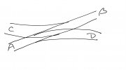
In any case looking at what Dave is doing on the kitchen table, I would have thought a good sized piece of Melamine would work for points being able to take it on and off the kitchen table with part built bits of track as ordered? I had a jig that I made when building 0 gauge track many moons ago that still lives in my loft for the day when I may get back into 0 gauge again, was on a length of chipboard that has seen many points built including 3 way and ‘nearly a slip NAS’. NAS was actually 2 interlaced points that I saw as a prototype at Chichester in my Selsey Light Railway book.

As you can see most of the routes from a slip are possible. But C-D is not without a triple shunt C-B, B-A, A-D.
22A4D204-1D78-4113-A29F-DD035279DDD9.jpeg
 
That's called a Barry Slip
Building your own track is certainly a worthwhile occupation when you have lots of points or near points (interlaced) required. You certainly save a great deal of wad a d get something that is not supplied commercially to boot. There was a time where it was not worthwhile to build plain track from scratch but I am not sure how the costs stack up now.

In any case looking at what Dave is doing on the kitchen table, I would have thought a good sized piece of Melamine would work for points being able to take it on and off the kitchen table with part built bits of track as ordered? I had a jig that I made when building 0 gauge track many moons ago that still lives in my loft for the day when I may get back into 0 gauge again, was on a length of chipboard that has seen many points built including 3 way and ‘nearly a slip NAS’. NAS was actually 2 interlaced points that I saw as a prototype at Chichester in my Selsey Light Railway book.

As you can see most of the routes from a slip are possible. But C-D is not without a triple shunt C-B, B-A, A-D.
View attachment 288941
That's called a Barry Slip, they weren't common but their were quite a few around the uk, although I'm not aware of any in Scotland so a little difficult to justify for a Scottish distillery layout.

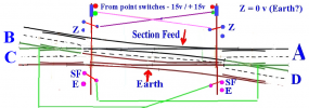
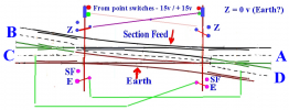
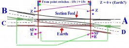
From memory, if using track power the best way I could think of wiring a Barry Slip was the same as a double slip.

David
 
That's called a Barry Slip

That's called a Barry Slip, they weren't common but their were quite a few around the uk, although I'm not aware of any in Scotland so a little difficult to justify for a Scottish distillery layout.

From memory, if using track power the best way I could think of wiring a Barry Slip was the same as a double slip.

David
Hm would need to dig the board out to see how I wired it but as it was all live frogs I think I wired it up as 2 conventional points with a changeover switch for each frog. It did mean that certain routes may have caused a short but never did in practice so I must have made additional isolations feeding the complete Barry Point from the centre and treating it as a single section. As the layout was not DCC this was not an issue.
 
..................... quite scary when you think about the up scaling I've jumped into.

David
Yup, for example if you started with a layout in N gauge, and went up to 00 gauge with the same layout, you'd need a baseboard four times as large (in area) :nod::nod:
 
Hm would need to dig the board out to see how I wired it but as it was all live frogs I think I wired it up as 2 conventional points with a changeover switch for each frog. It did mean that certain routes may have caused a short but never did in practice so I must have made additional isolations feeding the complete Barry Point from the centre and treating it as a single section. As the layout was not DCC this was not an issue.
I have these from days gone by.

I'm always amazed by the things I've saved over the years

David
 

Attachments

  • BarrySlipwiring15.png
    BarrySlipwiring15.png
    223 KB · Views: 0
  • BarrySlipwiring14.png
    BarrySlipwiring14.png
    210.8 KB · Views: 0
  • BarrySlip-Wiring13.jpg
    BarrySlip-Wiring13.jpg
    109.1 KB · Views: 0
I've found a mini blow torch to be the perfect tool for tinning the rails and brass strip I've used for my points. I then sweat them together with a 100w soldering iron, as this gives more control. Some mini mole grips are perfect to hold the rail in position without damaging it.
I have a 150w digital temperature controlled soldering station, not the cheapest bit of kit on my bench but worth the money, I haven't found anything I can't solder yet and that includes white metal.

I have been allocated or allowed, not sure which, a few hours to myself on Saturday to hopefully start fixing some rail down.

David
 
Back
Top