Reusing/repackaging NiMH batteries

Many thanks Phil. However I am not sure I understand some your terminology - FET, logic level outputs (1,2,3,4 5,L,6,7,8)? What functions are they involved in ? I do not need/wish to control lights on off with rc - is that what you are proposing with your install suggestion ? Testing with meter, what is suppling the voltage ?

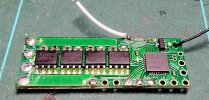
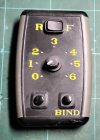
My inclination is to use fly leads off the battery terminal (nominal 13v) +/- to the +/- terminals on the buck. Set up buck's output voltage to 5v. Create circuit, with all on + buck output, return all to - buck output. Interpose switches on circuits for lights and smoke as required. Does this make sense ? Card will only be used for motor voltage control. Note white wire on card is not attached at one end to anything, what is its purpose ? Pictures, of now bare card and its supplied TX. Max
20240903_223025.jpg20240903_225358.jpg
 
Right, if you are only going to use the receiver to drive the motor, you only need to use the four pads at the opposite end to the aerial.

The receiver has outputs you could use for other things: Lights, smoke, to trigger sounds etc.

FET - Field Effect Transistor
A chunky electronic switch. - There are three of these on the board.
One is usually 'On' when the loco is set-to / moving forwards.
One is usually 'On' when the loco is set-to / moving backwards.
(These are referred to as Auto-Lights).
The third of these outputs, is often controlled by pressing the Bind button. - Could be used to trigger a whistle/horn on the sound card.

These three outputs are labelled 'A', 'B' and 'C' on the board.

The outputs 1-8 will be at either 3 3V or 0V. - These are the 'logic-level' signal voltages of the chips on the board.
These can be programmed to provide outputs when buttons / switches on the transmitter are operated. Give an output depending on which direction the speed controller is set to.
They can also be used as inputs, such as detecting the state of a reed-switch under the model, operated by a track-magnet. - This could be used to trigger the shuttle function built into the receiver, for example.

The 'L' input is used to monitor the voltage level of a single Lithium cell, when the input on the '+' and '-' pads is supplied by a booster.
In this sense, 'booster' is a device to increase the supply voltage to the receiver.

If you tell me what you would like to do (Eg. Use the Bind button for whistle / horn, use the other button to start/stop a diesel engine sound, or perhaps a Guards whistle / All-aboard announcement) this can be done.

General information on the receiver (if it had been supplied by RC Trains) is on this link:


As it was supplied by someone else, it could be configured to do different thing things on the A-C and 1-8 Pads, hence the need to test what happens.

PhilP
Is the Rx a Deltang type product?
 
Right, if you are only going to use the receiver to drive the motor, you only need to use the four pads at the opposite end to the aerial.

The receiver has outputs you could use for other things: Lights, smoke, to trigger sounds etc.

FET - Field Effect Transistor
A chunky electronic switch. - There are three of these on the board.
One is usually 'On' when the loco is set-to / moving forwards.
One is usually 'On' when the loco is set-to / moving backwards.
(These are referred to as Auto-Lights).
The third of these outputs, is often controlled by pressing the Bind button. - Could be used to trigger a whistle/horn on the sound card.

These three outputs are labelled 'A', 'B' and 'C' on the board.

The outputs 1-8 will be at either 3 3V or 0V. - These are the 'logic-level' signal voltages of the chips on the board.
These can be programmed to provide outputs when buttons / switches on the transmitter are operated. Give an output depending on which direction the speed controller is set to.
They can also be used as inputs, such as detecting the state of a reed-switch under the model, operated by a track-magnet. - This could be used to trigger the shuttle function built into the receiver, for example.

The 'L' input is used to monitor the voltage level of a single Lithium cell, when the input on the '+' and '-' pads is supplied by a booster.
In this sense, 'booster' is a device to increase the supply voltage to the receiver.

If you tell me what you would like to do (Eg. Use the Bind button for whistle / horn, use the other button to start/stop a diesel engine sound, or perhaps a Guards whistle / All-aboard announcement) this can be done.

General information on the receiver (if it had been supplied by RC Trains) is on this link:


As it was supplied by someone else, it could be configured to do different thing things on the A-C and 1-8 Pads, hence the need to test what happens.

PhilP

Many thanks for all the information. Given the 3 amp max I think it might be prudent to keep the lights and smoker of the card. However the thought of triggering the whistle alone is an attractive one. One question - what is that white lead, only soldered at one end, for ?

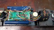
I have a plan. Yes, all the bits can now be chassis mounted. General layout below. Wiring can fit under the 10 cell battery box (the top of the motor housing lifts it up a couple of mm). Switch and socket open below water tank. Speaker, in the bunker ? Now need to wire it up and make sure it all works. Phil, do you sell speakers, as well as wiring looms and fuses ? Max.

20240904_125655.jpg
 
Many thanks for all the information. Given the 3 amp max I think it might be prudent to keep the lights and smoker of the card. However the thought of triggering the whistle alone is an attractive one. One question - what is that white lead, only soldered at one end, for ?

I have a plan. Yes, all the bits can now be chassis mounted. General layout below. Wiring can fit under the 10 cell battery box (the top of the motor housing lifts it up a couple of mm). Switch and socket open below water tank. Speaker, in the bunker ? Now need to wire it up and make sure it all works. Phil, do you sell speakers, as well as wiring looms and fuses ? Max.

View attachment 332432
Hi Max,
How much space do you have for the speaker? - I have many, but5not on the webby-site..

A LGB 5V smoke unit takes 700mA (0.7A)max.
Each 5V bulb is 50mA
The motor about 1.2A on stall, so plenty of headroom.

The white wire:
This could well be a connection to the 3 3V from the regulator on the receiver.. - A little difficult to see clearly in your picture.
This would mean 150 Ohm resistors for LEDs.

You could go to the Deltang website, and connection info is there.
We tend to supply the receivers with 100mm 'tails' for customers to connect to. - Many are wary of soldering to be honest. Well, finer stuff, anyway.

A receiver where Bakers Fluid has been used as flux, is not a pretty sight, after a winter in a shed or garage..

PhilP

Space is limited. I have a depth of 15 mm in the bunker. I would drill small holes to let the sound out. I'll send you a picture of what I am thinking of.

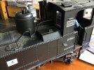
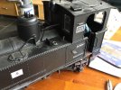
A little more work - removed 9 redundant 5 mm deep lugs inside the top of the body moulding. Took 3.5 mm off the top of the motor mount. Total 8.5 mm extra headroom in the body acheived. Shaved back the chimney. All to make sure battery pack and cards all fit nice and neat. I like to see a plan come together. As I said before you do not know what can be acheived until you have the article in your hands and have time to do a bit of codgitating. Max

Got the component layout sorted
20240905_113430.jpg

3.5 mm off the top sir ? And don't mess up the lugs.
20240905_112932.jpg

There's a lot of space to be found paring back the chimney and taking out non essential bits of plastic that intrude on the space you want to use. Every little helps.
20240905_112839.jpg
 
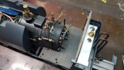
I am getting fed up of hiding On/Off switch plus charging socket so am coming round to the solution of putting them on the tank top with a small too box to hide them as seen below on my battery fixated former U.

IMG_1577.jpegIMG_1578.jpeg
 
Fine, as long as you remember where they are...

I have had one query, when I had installed something similarly..
Even though the information was in the instructions supplied with the loco. Granted, it was the following season, so the loco had been in storage, over winter.

Next version firmware on the Micron receivers, will have an 'e-switch' feature..
A concealed reed-switch will be able to be used to turn On/Off, or even used for higher current devices.

PhilP
Like the reed switch concept, must suggest it to Fosworks as I am so heavily committed to their products now. Still would need to locate the charge socket oh and fuse in a good accessible location like I suggested.
 
Like the reed switch concept, must suggest it to Fosworks as I am so heavily committed to their products now. Still would need to locate the charge socket oh and fuse in a good accessible location like I suggested.
In most locos, you can get away with the charge socket below the footplate, although on a Bachmann 10-wheeler, I have managed to install the charge socket and on/off switch in the hinged water filler ('cos it's oval).

For a fuse, you have to move with the times and use a polyswitch - you don't need access for that as it resets ;)
 
Under the running plate on my tank locos, use slider switches rather than toggles to hide them properly. Max
 
Under the running plate on my tank locos, use slider switches rather than toggles to hide them properly. Max
Yep, I used to favour slide switches, but have had three fail, so I have rather gone orf them :nerd::nerd:

In the end, on the Yeti, I used a toggle with a black rubber sheath (:lipssealed: ) on the lever - hides it sufficiently for average use, I don't do close up photo shoots ;)
 
Like the reed switch concept, must suggest it to Fosworks as I am so heavily committed to their products now. Still would need to locate the charge socket oh and fuse in a good accessible location like I suggested.
You may not need to..

Still finalising some of the details, but there will be a stand-alone option. - So you could use it with a Fosworks receiver.

PhilP
 
You may not need to..

Still finalising some of the details, but there will be a stand-alone option. - So you could use it with a Fosworks receiver.

PhilP
So it will be some kind of a latch reed?
 
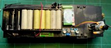
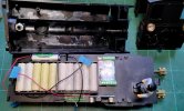
Thanks for all the advise. The batteries are all the same make. Removal of jackets caused by their method of installation - double sided sticky and hot glue (!) See first picture below. I have neatly re-wrapped each cell, ensuring an overlap, used masking tape.

I want to create an installation, cardsView attachment 332312, batteries & switchgear, that is all on the chassis, with only the lights body mounted with JST connections, to the body. Did that with my GRS L&B Manning Wardell. I wish to reuse the batteries, for convenience I want holders. I suppose I could use some of the very thin brass strip and low temp solder to create permant formations. I can always add strapping as a, literal, belt and braces job to secure. LGB body has 5 mounting screws, but 2x in side tank areas could be removed. It has not proved too traumatic getting in. Max

Please, oh please don't use masking or electrical tape for this purpose (or for covering soldered connections of wires)!!!

Buy heat shrink and invest in a heat gun to do a proper job of insulating the batteries and / or wires - glue eventually dies on both masking and electrical tape, neither provide proper heat insulation and the former does not provide proper insulation.

This is a custom made split 6A/Hr 14.8V LiIon battery pack with PCM for a Bachmann Fn3 Mallet - unit was finally built by Master Instruments here in Melbourne (LiIon batteries & PCM) with shrink wrapped components.

Notice my use of heat shrink to connect the wiring loom from the rear of the locomotive to the Bachmann adapter board - the connector for the 10-pin loom can just be seen to the right of the footplate along with the 4-wire loom.

20240905_203552.jpg

In this shot the batteries are inside the saddle tanks (with the PCM just visible). The CVP Airwire receiver and LokSound 5XL are installed in the bunker with a 10 wire loom to the Bachmann adapter board, along with a 4 wire loom for battery feed and decoder "track out" - when the switch points to the charging socket the RCA can be used to program the decoder (whilst charging the battery) - pointed the other way is the run position.

20240905_212320.jpg

Oil bunker covers the switch panel and just lifts off - cab light and rear headlight wires have a heat shrink tube around them to help disguise the coloured wires.

If people are interested I can put up the wiring schematic of how I did this - the locomotive remains intact electrically - unlike the 3-truck Shay I had as my first Fn3 project (it was gutted and a wreck when I bought it, as documented elsewhere).

I have no intention of running on track power but to do so is to put the Bachmann dummy plug back in the motherboard and change the motherboard switches.

Everything works (firebox flicker, sound, etc.) except for the Bachmann smoke unit - not fussed about it but I may fit an ESU smoke unit at some stage in the future.

Cheers,
 
Please, oh please don't use masking or electrical tape for this purpose (or for covering soldered connections of wires)!!!

Buy heat shrink and invest in a heat gun to do a proper job of insulating the batteries and / or wires - glue eventually dies on both masking and electrical tape, neither provide proper heat insulation and the former does not provide proper insulation.

This is a custom made split 6A/Hr 14.8V LiIon battery pack with PCM for a Bachmann Fn3 Mallet - unit was finally built by Master Instruments here in Melbourne (LiIon batteries & PCM) with shrink wrapped components.

Notice my use of heat shrink to connect the wiring loom from the rear of the locomotive to the Bachmann adapter board - the connector for the 10-pin loom can just be seen to the right of the footplate along with the 4-wire loom.

View attachment 332670

In this shot the batteries are inside the saddle tanks (with the PCM just visible). The CVP Airwire receiver and LokSound 5XL are installed in the bunker with a 10 wire loom to the Bachmann adapter board, along with a 4 wire loom for battery feed and decoder "track out" - when the switch points to the charging socket the RCA can be used to program the decoder (whilst charging the battery) - pointed the other way is the run position.

View attachment 332671

Oil bunker covers the switch panel and just lifts off - cab light and rear headlight wires have a heat shrink tube around them to help disguise the coloured wires.

If people are interested I can put up the wiring schematic of how I did this - the locomotive remains intact electrically - unlike the 3-truck Shay I had as my first Fn3 project (it was gutted and a wreck when I bought it, as documented elsewhere).

I have no intention of running on track power but to do so is to put the Bachmann dummy plug back in the motherboard and change the motherboard switches.

Everything works (firebox flicker, sound, etc.) except for the Bachmann smoke unit - not fussed about it but I may fit an ESU smoke unit at some stage in the future.

Cheers,

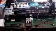
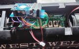
Now here is a coincidence. Next on the to do's is get the Bachmann 2-6-6-2 + ESU finished. This is just a test rig to make sure it all works. The final instal will get rid of the Bachmann adapter and get the ESU to fit direct to the Bachman motherboard, so we can get it all "under the hood". A friend is working on it for me. If we can't get it to work I will go with the bunker option too. Speaker 6.5 cm Visaton not the cube in the test rig. Batteries in the tanks.

Your information is very useful. The masking tape is only temporary. Max

20240912_133550.jpg20240912_133608.jpg
 
Back
Top