Oh do disagreement on that, but as I have a Megacontrol board already and servos are quite reasonable the cost per point is somewhat cheeper. Plus I want to use the Cobolt levers that I have thus the complexities of DCC with points would be a pain plus a quite expensive cost.Were you looking at the correct item? Considering it is both a drive and DCC decoder in one I thought the price, € 40, pretty reasonable.
You are using an out of date browser. It may not display this or other websites correctly.
You should upgrade or use an alternative browser.
You should upgrade or use an alternative browser.
Servo Controlled Points
- Thread starter GAP
- Start date
The Shed
Citizen of the Republic of the North East.
Have you thought about using a Servo to provide Linear movement?
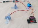
Also notice you mentioned on another Forum! about using Micro switches operated by a Servo.
Post #279 What have you been printing.

Also notice you mentioned on another Forum! about using Micro switches operated by a Servo.
Post #279 What have you been printing.
Have you tried liner servos? Have a couple of nice small ones that I got a while back but not tried them out as they have different plug (smaller than normal) and I need to get to the Aircraft Shop when they are open to ask for a converter wire. I know order on the net but I am unsure of the spec and name of either plug. That is when shopping in a real shop comes to the front.Have you thought about using a Servo to provide Linear movement?
View attachment 282161
Also notice you mentioned on another Forum! about using Micro switches operated by a Servo.
Post #279 What have you been printing.
Greg Elmassian
Guest
I think the challenges with servos outdoors is moisture resistance. I've been through a number of these, and bottom line is it's hard to seal the area around the servo shaft.
Also maybe not in the UK, but in the US, heat can be the enemy, causing moisture to vaporize and then condense where you don't want it.
Sunlight can affect plastic parts, and I know the picture above is an example, but that clear plastic in the sun would get eaten alive by UV.
What I have seen that works after some tweaks is an enclosure about the size of the LGB motor box, with the gears inside, and grease packed around the servo shaft and weep holes in the bottom corners of the enclosure to expel the condensation that inevitably forms, since the box cannot be hermetically sealed if it is to move a throwbar.
I worked for quite a time with DCC drives that had the decoder and a small servo and throw system.
Greg
The UK climate seems to be getting hotter and Wetter..
As Greg says, condensation is the biggest problem, then heat-soak.
Anything placed 'under' the road-bed, will get wet. - anything at ground-level, in a hole, will be flooded at some point.
My best, is an 'equipment cabinet' with the servo etc in it.
The bottom is 'open' - needed for the linkage, and means the equipment can breath.
Black is not the best colour, as it absorbs more heat.
PhilP
Greg Elmassian
Guest
Yep, and it also cools fastest at night, black is a great radiator when the sun is not shining... a black box outside where it can get sun is the ultimate moisture pump!
While the good news is that it gets hot and will boil moisture out well, as soon as the sun goes down, it cools more rapidly, and sucks in that nice cool moist air!
Greg
While the good news is that it gets hot and will boil moisture out well, as soon as the sun goes down, it cools more rapidly, and sucks in that nice cool moist air!
Greg
GAP
G Scale Model Trains, 1:1 Sugar Cane Trains
I am using waterproof servos as used in model boats so moisture ingress should not be an issue. I can put some silicon grease (as used by my pool serviceman to seal the filter) around the shaft for extra protection.
I have a somewhat unique situation in the layout being elevated and having an irrigation system running under it so water on both sides which is why I went waterproof servos and sealed enclosures for the electronics.
I am drawing on my aircraft maintenance experience here, condensation was a big issue in the avionics bays.
I have had suggestions of using silica gel or rice to reduce condensation as well.
"Also notice you mentioned on another Forum! about using Micro switches operated by a Servo."
Yes as the testers have 3 outputs I can use a second servo to operate either a semaphore signal or open and close a microswitch that would turn on and off an LED.
The micro-switch idea is a modified version of what I used on a HO layout to drive indicator lights on a switch panel, the switch was changed by a small pin protruding under a PECO solenoid point motor. Just replacing the pin with a servo.
The idea in post #279 is the type of thing I was thinking about.
LEDs out in the full sun will be hard to see if used as a signal, but OK as an indicator on the switch panel.
I am using waterproof servos as used in model
Should be plain sailing thenI am drawing on my aircraft maintenance experience here
The Shed
Citizen of the Republic of the North East.
Last edited:
GAP
G Scale Model Trains, 1:1 Sugar Cane Trains
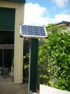
The solar battery array has been installed so I now have the start of a 5V bus to run the servos.
Solar panel
Charge controller and 5V Buck Converter
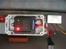
Battery, Charge Controller & Buck Converter installed.
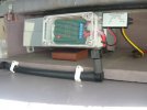
And yes I am using irrigation pipe as conduit, mainly because it is cheaper than electrical conduit, it is waterproof, is readily available (comes in 2 sizes 13mm &18mm) and it cuts easily (doesn't take like chicken though
 ).
).
Solar panel

Charge controller and 5V Buck Converter

Battery, Charge Controller & Buck Converter installed.

And yes I am using irrigation pipe as conduit, mainly because it is cheaper than electrical conduit, it is waterproof, is readily available (comes in 2 sizes 13mm &18mm) and it cuts easily (doesn't take like chicken though
GAP
G Scale Model Trains, 1:1 Sugar Cane Trains
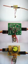
I have modified all 12 of my Servo Testers, so now I am ready to set them up on the layout.
I will be putting each one next its relevant point so that way I can adjust with a bit of ease.
They will be housed in plastic food containers, with a seal-able lid under the baseboard, we have had torrential rain this week and where I am planning on putting is still dry so they should be OK, the only water that gets under there is from the irrigation and it is only a fine mist anyway.
I added a On/Off switch for the 5V bus that I had in a box it is rated at 500V and 30A so I think it should handle a 5V 3A bus OK.
A picture of the way I modified the testers, in the top view Power on the Right, Servo on the Left and switch input at the bottom.

GAP
G Scale Model Trains, 1:1 Sugar Cane Trains
I installed one servo tester, wired it up to the 5V the bus and mounted a switch to the control panel.
Next I installed a servo next to a point and connected it to the tester.
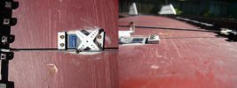
Following that I connected the servo horn to the point throwbar via a control rod with a clevis pin at one end, on the other end of the control rod at the horn I put a "Linkage Stopper" (these are used by the model aircraft people quite extensively).
The stopper has a grub screw adjustment so when I set the servo travel extremities using the 2 pots I could make fine adjustments to relieve any residual tension being applied to the control rod.
As the point I started with was on a crossover, I attached another servo to the other point and connected it to one of the tester outputs (there are 3) and now both points change at the same time controlled from the one control panel switch.
Now that I have it all working I will proceed with installing the rest of the servos to my points (12 of them)
The servos I am using are waterproof and are mounted under the baseboard.
I ran my irrigation sprays that are under the baseboard and no sign of any part being wet.
We also had 4 days of heavy rain and no water got under the baseboard everything was dry.
I am going to put a smear of silicone grease around the servo shaft to increase water repellence around its entry point.
I am using double walled heatshrink with a glue inside to keep moisture out of wiring joints.
Picture of the control rod showing the clevis pin and the linkage stopper.

Last edited:
Greg Elmassian
Guest
So in relation to normal up (sky) and down (earth) is the right-hand picture upside down?
Greg
Greg
I can answer this one...So in relation to normal up (sky) and down (earth) is the right-hand picture upside down?
Greg
No..
The body of the servo is set into the baseboard, and the linkage is above the board. - You can just make-out the turnout operating arm, on the right.
PhilP
Greg Elmassian
Guest
gap said: "The servos I am using are waterproof and are mounted under the baseboard."
but the picture and philP says not under the baseboard, but set into a hole cut into the baseboard. Thus waterproof is all the more important.
It seems the toughest place to waterproof is the shaft coming out...
Will the final installation add a cover on the top?
Greg
but the picture and philP says not under the baseboard, but set into a hole cut into the baseboard. Thus waterproof is all the more important.
It seems the toughest place to waterproof is the shaft coming out...
Will the final installation add a cover on the top?
Greg
The combination of damp and electricity, is the biggest killer, in my experience..
One of the best things you can do, is turn everything off when not in use..
The slightest film of damp, combined with even a small residual current in the electronics, will cause the print on circuit boards to migrate, due to electrolysis... - You come to repair a fault, and find tracks on the board have 'disappeared'!
PhilP

