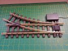
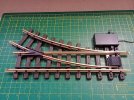
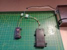
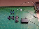
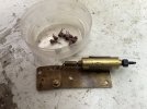
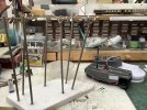
Continuation of control of the EVO-S.
To recap for normal DCC use, simple and straightforward to setup and operate.
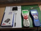
Manual control with LGB technology with anyone of the following, 5075N, 5175, 51750, 51755, PIKO 35260, or a homebrew switch setup that follows the original LGB design, for activation of the EVO-S, requires holding the switch in the correct operating position for at least three seconds for the EVO-S to complete the operation of moving the point blades.
This of course is not going to be accomplished with Automation equipment, which by its nature is either a momentary contact via a mechanical or electronic activation, or some form of Detection, as there is no delay normally built in, the EVO-S will be unable to operate correctly.
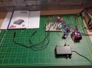
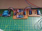
Depending on which form of Activation or Detection is in use, normally usually as only in two formats, active High or active Low, this governs the design of the first module as described as Input/Output, all this does is register an Input and pass it through as the correct Output.
In this demo, active Low to Trigger the start of the sequence, includes the circuitry to convert to active High to Trigger the Timer Delay Board.
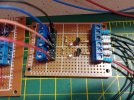
From the Input/Output board to the Timer Delay Board as in active High, which in turn activates the Timer, which is adjustable in Time.
Again depending on the Input to the Relay Module, the output of the Timer Delay Board will be either active High or active Low.
The output in this demo is active Low to Trigger the Relay Module.
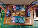
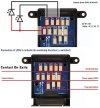
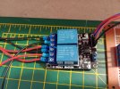
2 Channel Relay Module, configured as a DPDT Reverse, to switch POS or NEG to power the EVO-S, to move forwards or backwards.
The Timer as set in Time, to hold either Relay ON, for sufficiently long enough for the EVO-S to complete its normal sequence of operation.
There will be short video in due course, to show the EVO-S in operation.
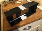
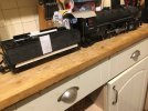 shut; a Bachmann Annie tender body (stretched and sides smoothed out) and much plasticard/ styrene, along with bits from the spares box.
 shut; a Bachmann Annie tender body (stretched and sides smoothed out) and much plasticard/ styrene, along with bits from the spares box.
