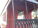
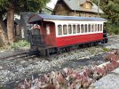
Pretty much on the home straight now, thank goodness says Matt!
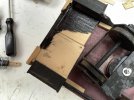
Couplings have given me much pause for thought as I mentioned in one of my earlier posts. The simples option would have been to fit LGB bogies with LGB couplings as those are my chosen couplings. But as I had built the kit bogies I decided to tough it out. Here you can see I have fitted 2 pieces of 11/44 40 mm long and with one piece cut to give an 82mm width. This was deliberate (I can sometimes think ahead) so that the steps would be able to butt up to these bits when glued in place, thus giving these vulnerable parts a more secure hold.
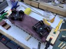
Below I have cut some 4x18mm strip to act as the buffer beam. Though there 2x 3d printed ones included in the kit as these have fittings for 2 buffers as can be seen on Matt’s build, referred to earlier this was not for me. Incidentally the Timber are standard sizes available in the timber moldings section found in Wicks or BnQ. Note how I have cut out a slot for the coupling to allow for sharpe Tramway (LGB R1) curves.
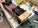
I did some test holes to temporarily fit the couplings to see how much I needed to adapt things.
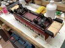
Here I have used an LGB coupling in the hole seen above and you can see that I am pretty much spot on. As can be seen the footstepps have also been fitted with sundry bits of scrap wood to help hide joints.
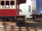
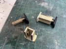
Thus I could move to the next stage which was to cut some wood for the coupling to be mounted in place. This was a strip of the 4x18mm cut to 7 wide by 50 long thus fitting inside the LGB coupling. The holes were drilled out and LGB screws used to hold the coupling hook/loop assembly and spring in place as seen. The other hole was for the mount but this gave too much droop. So the wood was thinned further to match the depth of the LGB coupling groove and a hole drilled nearer the coupling. While this was being cut with a razor saw the screw was also shorted in situ thus ensuring that it did not drag on the base wood. Another mounting hole was drilled in the base wood so that the coupling could swing nicely left and right. This was then tested out and washers used to give perfect height, one was also mounted next to the screw head to give smooth swing left and right with the screw just on interference fit.
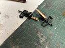
In the end as you can see below the pivot was made closer to the actual coupling.
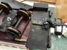
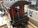
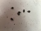
Next up was to fit the roof pots, eight are supplied and these are not ventilators as they are sometimes called but roof lamp ventilators and on the bogie car you can clearly see that one is mounted over the platform each end. Why would you need fresh air in that location? Clearly light is the priority. So they have been mounted at 3/8 and 15.5cm positions from each end. But first I drilled a hole in the centre to glue in a small pin to give extra holding when glued in place. Holes were then drilled at the marks for glueing in place. Oh yes the nail heads were also cut off.
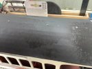
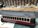
I have also fitted the end Roof Support Wires and 3d printed Balcony Ends. The wires go through holes each side of the flat base into the platform to give a more secure hold. The holes were drilled in my pillar drill. These will get a hidden soldered top to keep them neat and fit inside the additional roof end that I mentioned earlier. I have also elected not to use the 4 Window fill ins that are present in the mould for each side. I suggest that these be left in place when you remove the sides from the frets should you wish for them to be present.
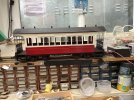
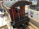
I am not to happy with the roof fit as yet but hope that a screw will keep things in place once fitted.
Left to complete are central end buffers, Hand Brakes (supplied in the kit), Glazing (supplied in the kit), lettering and that wire just mentioned.
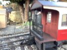
All in all I am very happy with the kit, whilst I have made many alterations to suit my personal needs I think that you can see from what has been done thus far that this is a rather nice kit that I wish Matt well with production of.


