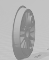
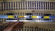
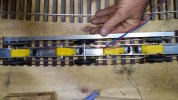
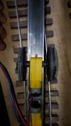
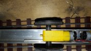
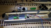
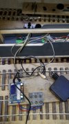
So, a bit of advice about "blind" drivers (no flanges).
............
Anyway after a day of playing, i think i know where the hinges must be, surprise: almost prototypical and the pivoting points: surprise: almost prototypical
Also figured out some other needed measurements, yes it was a fun learning game
Copy and past anyone can do, but do you know what kind of knowledge there is behind it?!?!?!?
Keep on learning and dont be afraid to experiment and fail
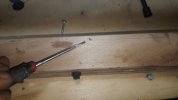
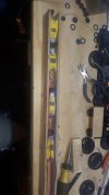
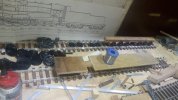
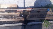
Below every picture there is a explanation and a question or two.
Sorry if i named the things wrong, English is not my native language, and this is pretty technical English and not chit chat English
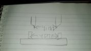
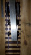
I will keep the 41 mm from back to back from the flange.
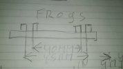
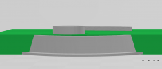
As you can see the clearance is just 2 mm at each wheel, to avoid problems the "bearing surface"of the wheels will go to 6mm each instead of 5 mm, the blind ones will go to 7mm(the flange is 1mm thick btw)
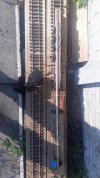
From the frog side to the rail side is 2.5mm in width inside
.
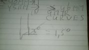
To let her drive over the frogs i will change the angle from 3 to 1.5 degree on the unflanged wheels, to help her on the frogs...will it help??? dont have a clue, we will see.
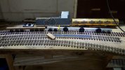
In the most desperate case i can make my curves a full mm wider to 46mm instead of 45mm
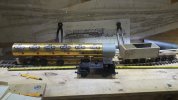
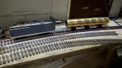
The aa20 in approximate dimensions(2cm to low btw, length is prototypical), in front just for the giggles the terrier loco. I could not resist to make this picture, sorry
Tray/drawer on the tender is just a idea to give a idea for the size.
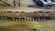
Hinges of the tender are prototypical not in the middle, seems to work out very good.
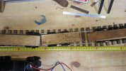
The back support, THE link in between the drivering part and the feeding(Tender--->it was partially mechanical feeding the boiler not two fireman but one!) part, but the caring part.
As per prototypical there are some hinges that can not be done if you want to have it on a 4 meter radii curve.
Between the driver part and the bearing/supporting part there can be one hinge, i am thinking of a 2 hinged part between those two, the same for between the bearing part and the tender, that must be two.
If you look close at the drawing you can see that there is a two layer of steel that is on top of the bearing part.
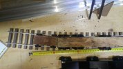

Front support/boogie/bearing part, between those two i am in doubt one hinge or two parted hinge...
I think one hinge and the piviting point closer to the loco.
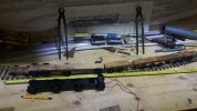
The body of the drivers is going to be much smaller/thinner 33 mm (was 35mm) to give more clearance and more play to the flanged wheels, it will gain 1 mm on the track without building/designing a track only for her.
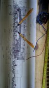
In the red markings on the drawing you will see where the pivoting points will be in thick red, in thin red you will see the hinged parts.
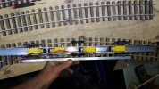
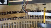
The tips of the ball pens are pointing to the support that will slide over the driver body to give the much needed 8mm! side clearance.
Incl the 2mm extra clearance on the middle blind wheels and the extra 1mm clearance on both flanged wheels it could be possible to let her drive on a 4 meter radii curve and let her pass over some turnouts crossover etc (minimum 4.60 radii!!!) without trouble.
Even with all those adaptions she will still behave like her prototypical counterpart, especially on/with the pivoting points/side ways movement/ boiler bearing stuff.
I must admit i learn a lot more of things from the real life locos(/and tracks!+wheels), more than i would thought, my mechanical/engineering side was always strong, but never to old to learn.
Btw this is one of the many drawing i downloaded from the internet, this is just a guideline, only know width is the cab (3.08 meters) and the cylinders.
Thanks for reading, i hope you enjoy my endeavors, but she is tricky
With best regards Igor.


